
User's Guide
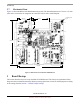
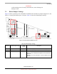
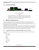
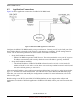
Table Of Contents
- About This Book
- 1 Introduction
- 2 MPC837xE-RDS Board
- 2.1 Board-Level Functions
- 2.1.1 Reset and Reset Configurations
- 2.1.2 External Interrupts
- 2.1.3 Clock Distribution
- 2.1.4 DDR2 SDRAM Controller
- 2.1.5 Local Bus Controller
- 2.1.6 Flash Memory
- 2.1.7 I2C
- 2.1.8 SATA Controller
- 2.1.9 PCI Express Interface (PCI-E & Mini PCI-E)
- 2.1.10 10/100/1000 BaseT Interface
- 2.1.11 RS-232 Port
- 2.1.12 USB 2.0 Interface
- 2.1.13 PCI Subsystem
- 2.1.14 COP/JTAG Port
- 2.2 MPC837xE-RDS Assembly
- 2.3 Connectors
- 2.4 LEDs
- 2.5 MPC837xE-RDS Board Configuration
- 2.6 Specifications
- 2.7 Mechanical Data
- 2.1 Board-Level Functions
- 3 Board Bootup
- 4 MPC837xE-RDS Software
- 5 Unit Assembly
- MPC837xE-RDS

Unit Assembly
MPC837xE-RDS, Rev. 1.0
Freescale Semiconductor 37
Preliminary, Subject to Change without Notice
5 Unit Assembly
The assembled unit is composed of the board assembly, an enclosure, screws, and other parts. The
instructions in this section apply if you need to assemble or reassemble the product or add peripherals
mentioned.
5.1 Assembling the Enclosure and Board Assembly
Assembling the board into the enclosure requires screwing the board onto the base, then screwing the top
and base together.
1. Place the base on a flat surface.
2. Set the board assembly in the base so the connectors and LEDs fit perfectly and the board’s
mounting holes align with the base’s mating holes.
3. With four screws and washers, screw the board to the base.
4. Align the top with the base, with the Freescale logo nearest the rear panel (connector side).
5. Screw the parts together from the bottom side of the base using four screws.
5.2 Attaching a Wi-Fi Card to the Product
Attaching the Wi-Fi card to the product requires separating the top of the enclosure from the unit, plugging
a Wi-Fi card into a mini PCI slot, installing the antenna cable into the Wi-Fi card, then reassembling the
the product.
CAUTION
Use a 3.3 V mini PCI card only. Power down before insertion or removal.
1. From the bottom of the assembled unit, remove the four screws.
2. Turn the unit right side up, plug in the Wi-Fi card, then latch it. See Figure 16 for positioning
depiction.
3. Install the antenna cable into the Wi-Fi card connector, then select the proper holes on the panel (4
on rear panel and 2 on front panel) to position the antenna.
4. Re-assemble using Steps 4 and 5 of Section 5.1, Assembling the Enclosure and Board Assembly.
5.3 Attaching a SATA hard disk to the Product
Attaching a SATA hard disk to the product requires disassembling the unit into the enclosure top and
bottom and the board assembly, inserting the hard disk, installing the cable, then re-assembling the
product.
1. Disassemble the entire unit.
2. Plug the SATA cable to J11 at the bottom side of PCBA.
3. Release the hard disk tray on the enclosure base, then position the hard disk in it.
4. Plug the other end of the SATA cable to hard disk, then position the tray in the base.