
User's Guide
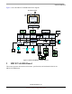
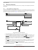
Table Of Contents
- About This Book
- 1 Introduction
- 2 MPC837xE-RDS Board
- 2.1 Board-Level Functions
- 2.1.1 Reset and Reset Configurations
- 2.1.2 External Interrupts
- 2.1.3 Clock Distribution
- 2.1.4 DDR2 SDRAM Controller
- 2.1.5 Local Bus Controller
- 2.1.6 Flash Memory
- 2.1.7 I2C
- 2.1.8 SATA Controller
- 2.1.9 PCI Express Interface (PCI-E & Mini PCI-E)
- 2.1.10 10/100/1000 BaseT Interface
- 2.1.11 RS-232 Port
- 2.1.12 USB 2.0 Interface
- 2.1.13 PCI Subsystem
- 2.1.14 COP/JTAG Port
- 2.2 MPC837xE-RDS Assembly
- 2.3 Connectors
- 2.4 LEDs
- 2.5 MPC837xE-RDS Board Configuration
- 2.6 Specifications
- 2.7 Mechanical Data
- 2.1 Board-Level Functions
- 3 Board Bootup
- 4 MPC837xE-RDS Software
- 5 Unit Assembly
- MPC837xE-RDS

MPC837xE-RDS, Rev. 1.0
Freescale Semiconductor 5
Preliminary, Subject to Change without Notice
About This Book
This document presents system architecture, board-level functions, external connections, and software
features for the MPC837xE-RDS board. It provides guidance of how to operate this product, making it
easy for the user to connect with the outside world. The front part of this book focuses primarily on the
board and functions. The latter part of the book focuses on the mechanical aspects.
Audience
Users who want to become familiar with the MPC837xE-RDS board, its characteristics, and how to
program the device.
Organization
Chapter 1, Introduction, describes the features and block diagram for the MPC837xE-RDS board.
Chapter 2, MPC837xE-RDS Board, describes the board in terms of its hardware: board-level functions,
connectors, configurations, and board mechanical data.
Chapter 3, Board Bootup, describes the board settings and physical connections needed to boot the
MPC837xE-RDS board.
Chapter 4, MPC837xE-RDS Software, describes the main software features for MPC837xE-RDS board.
Definitions, Acronyms, and Abbreviations
The following list defines the acronyms and abbreviations used in this document.
NAS Network-Attached Storage
RAID Redundant Array of Inexpensive Disks
CPU Central Processing Unit
PoE Power over Ethernet
DDR2 SDRAM Double-Data-Rate Two Synchronous Dynamic Random Access Memory
NOR Flash Nor Gate Flash
eTSEC Enhanced Three-Speed Ethernet Controller
RGMII Reduced Gigabit Media Independent Interface
WAN Wide Area Network
LAN Local Area Network
USB Universal Serial Bus
ULPI USB Low-Pin Count Interface
SATA Serial Advanced Technology Attachment (computer bus)
PCI Peripheral Component Interconnect (computer bus)
PCI-E Peripheral Component Interconnect Express (computer bus)
SDHC Secure Digital High Capacity (SD 2.0 memory card)