
User's Guide
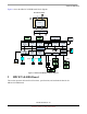
Table Of Contents
- About This Book
- 1 Introduction
- 2 MPC837xE-RDS Board
- 2.1 Board-Level Functions
- 2.1.1 Reset and Reset Configurations
- 2.1.2 External Interrupts
- 2.1.3 Clock Distribution
- 2.1.4 DDR2 SDRAM Controller
- 2.1.5 Local Bus Controller
- 2.1.6 Flash Memory
- 2.1.7 I2C
- 2.1.8 SATA Controller
- 2.1.9 PCI Express Interface (PCI-E & Mini PCI-E)
- 2.1.10 10/100/1000 BaseT Interface
- 2.1.11 RS-232 Port
- 2.1.12 USB 2.0 Interface
- 2.1.13 PCI Subsystem
- 2.1.14 COP/JTAG Port
- 2.2 MPC837xE-RDS Assembly
- 2.3 Connectors
- 2.4 LEDs
- 2.5 MPC837xE-RDS Board Configuration
- 2.6 Specifications
- 2.7 Mechanical Data
- 2.1 Board-Level Functions
- 3 Board Bootup
- 4 MPC837xE-RDS Software
- 5 Unit Assembly
- MPC837xE-RDS

Introduction
MPC837xE-RDS, Rev. 1.0
Freescale Semiconductor 7
Preliminary, Subject to Change without Notice
1Introduction
This section presents the features and block diagram for the MPC837xE-RDS board.
1.1 Overview
The MPC837xE-RDS is a reference design based on the MPC8377E PowerQUICC
TM
II Pro processor. It
supports applications of Wi-Fi Router, DMS (Digital Media Server), NAS with RAID, or Office in BOX,
etc. The documentation for manufacturing the MPC837xE-RDS—including schematic, Gerber files,
reference software, Bill Of Material (BOM)—is on the product CD. With the documentation, original
equipment manufacturers (OEMs) and original design manufacturers (ODMs) can accelerate the
development process and speed time-to-market for their real product.
1.2 Features
This section presents the features, specification, and block diagram of the MPC837xE-RDS board. The
features are as follows:
•CPU
— Freescale MPC8377E @ 667 MHz
•Power
— PoE power solution based on LM5072 up to 30 W output, designed as one daughter
module board
— 48 V DC input used as the alternative power source when PoE is not available
• Memory subsystem
— On-board 512-MByte DDR2 unbuffered SDRAM
— 64-MByte NOR Flash
• Interfaces
— 10/100/1000 BaseT Ethernet ports
– eTSEC1
– RGMII interface: WAN, 1 x 10/100/1000 BaseT with RJ-45 interface, using
Realtek
TM
RTL8211B single port 10/100/1000 BaseT PHY. This port
supports PoE feature
– eTSEC 2
– RGMII interface: LAN, 1 x 10/100/1000 BaseT with RJ-45 interface, using
Realtek
TM
RTL8211B single port 10/100/1000 BaseT PHY
— USB 2.0 Host
– ULPI interface: 1 x USB 2.0 Type A Receptacle interface, using SMSC
TM
USB3300 Hi-Speed USB PHY
— Serial ATA Controller