
User's Guide
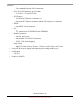
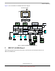
Table Of Contents
- About This Book
- 1 Introduction
- 2 MPC837xE-RDS Board
- 2.1 Board-Level Functions
- 2.1.1 Reset and Reset Configurations
- 2.1.2 External Interrupts
- 2.1.3 Clock Distribution
- 2.1.4 DDR2 SDRAM Controller
- 2.1.5 Local Bus Controller
- 2.1.6 Flash Memory
- 2.1.7 I2C
- 2.1.8 SATA Controller
- 2.1.9 PCI Express Interface (PCI-E & Mini PCI-E)
- 2.1.10 10/100/1000 BaseT Interface
- 2.1.11 RS-232 Port
- 2.1.12 USB 2.0 Interface
- 2.1.13 PCI Subsystem
- 2.1.14 COP/JTAG Port
- 2.2 MPC837xE-RDS Assembly
- 2.3 Connectors
- 2.4 LEDs
- 2.5 MPC837xE-RDS Board Configuration
- 2.6 Specifications
- 2.7 Mechanical Data
- 2.1 Board-Level Functions
- 3 Board Bootup
- 4 MPC837xE-RDS Software
- 5 Unit Assembly
- MPC837xE-RDS

MPC837xE-RDS Board
MPC837xE-RDS, Rev. 1.0
Freescale Semiconductor 9
Preliminary, Subject to Change without Notice
Figure 1 shows the MPC837xE-RDS board block diagram.
Figure 1. MPC837xE-RDS Board Block Diagram
2 MPC837xE-RDS Board
This section presents the board-level functions, specifications, and mechanical data for the
MPC837xE-RDS board.
e 300 Core
32 KB
D-Cache
DUART
Dual I
2
C
Timers
GPIO, SPI
Interrupt
Controller
Security
DDR
Controller
Local Bus
USB
Hi-Speed
Host Device
PHY
ULPI
RGMII
RGMII
RTL8211
Nor Flash
(x 16)
PCI
DDR2 (x64)
I
2
C1
PHY
UART1
DDR2
MPC8377E
PCI-E
SATAII
eSATA
con
PCI
SD
miniPCI
Socket
miniPCI
Socket
SD
Card
Clock Gen
PCI- E 1X
JTAG/COP
RTL8211
PHY PHY
EEPROM
miniPCI-E
Socket
miniPCI-E
Socket
USB Type A
LM5072
48V PoE 48V AC/DC
1.8 1.5 1.0
5V 3.3V
PoE
Card
32 KB
I-Cache
10/100/1000
Ethernet
eTSEC1
10/100/1000
Ethernet
eTSEC2