TWR-MCF52259-Ethenet Hareesh S Sr.FAE TM Freescale Semiconductor Confidential and Proprietary Information. Freescale™ and the Freescale logo are trademarks of Freescale Semiconductor, Inc. All other product or service names are the property of their respective owners. © Freescale Semiconductor, Inc. 2006.
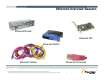
Ethernet Overview Session Ethernet Router Ethernet NIC Ethernet Switch Ethernet Cables Freescale Semiconductor Confidential and Proprietary Information. Freescale™ and the Freescale logo are trademarks of Freescale Semiconductor, Inc. All other product or service names are the property of their respective owners. © Freescale Semiconductor, Inc. 2006.
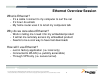
Ethernet Overview Session What is Ethernet? • • • It’s a cable I connect to my computer to surf the net It’s how I do emails My home router uses it to let all my computers talk Why do we care about Ethernet? • • • Work is telling me I need it for my embedded product It will let me remotely access my embedded product Seems to be a cool way to have fast downloads How will I use Ethernet? • • • Just in factory application (i.e. local only) Connected to WLAN (i.e. publicly accessible) Through VPN only (i.
Ethernet Ethernet defines the mechanical/electrical connection between devices (the physical layer). Ethernet also defines a protocol used to communicate between multiple devices (the MAC layer). Ethernet is defined by the IEEE 802.3 standard Freescale Semiconductor Confidential and Proprietary Information. Freescale™ and the Freescale logo are trademarks of Freescale Semiconductor, Inc. All other product or service names are the property of their respective owners. © Freescale Semiconductor, Inc. 2006.
Generic ColdFire® Board Layout of Ethernet MII – Media Independent Interface ColdFire® PHY On-Chip Ethernet MAC-Media Access Controller PHY-Physical Layer Magnetics Isolation And optional PoE Freescale Semiconductor Confidential and Proprietary Information. Freescale™ and the Freescale logo are trademarks of Freescale Semiconductor, Inc. All other product or service names are the property of their respective owners. © Freescale Semiconductor, Inc. 2006.
M52233DEMO Board Layout of Ethernet MAC-Media Access Controller PHY-Physical Layer Cable Magnetics RJ45 Isolation And optional PoE Jack RJ45 Network On-Chip Ethernet w/ PHY PHY MCF5223x Line Voltage Levels +2.8V or -2.8VDC Freescale Semiconductor Confidential and Proprietary Information. Freescale™ and the Freescale logo are trademarks of Freescale Semiconductor, Inc. All other product or service names are the property of their respective owners. © Freescale Semiconductor, Inc. 2006.
Ethernet Overview Physical Session Connectors • RJ-45 Cables • CAT-5 24 AWG solid bare copper Four unbounded twisted pairs Freescale Semiconductor Confidential and Proprietary Information. Freescale™ and the Freescale logo are trademarks of Freescale Semiconductor, Inc. All other product or service names are the property of their respective owners. © Freescale Semiconductor, Inc. 2006.
Ethernet Cable: Straight Through Pinout The following table demonstrates the proper color scheme. Wire pair #1: Wire pair #2: Wire pair #3: Wire pair #4: White/Blue Blue RJ-45 Pin Sign al Directi on RJ-45 Pin 1 TX+ ---> 1 White/Orange Orange 2 TX- ---> 2 3 RX+ <--- 3 White/Green Green 4 - - 4 5 - - 5 6 RX- <--- 6 7 - - 7 8 - - 8 White/Brown Brown Source: http://www.netspec.com/helpdesk/wiredoc.html Freescale Semiconductor Confidential and Proprietary Information.
Ethernet Cable: Crossover Pinout The following is the proper pin out and cable pair/color order for the "crossover" end. Pair#2 is connected to pins 1 and 2 like this: Pin 1 wire color: white/green Pin 2 wire color: green Pair#3 is connected to pins 3 and 6 like this: Pin 3 wire color: white/orange Pin 6 wire color: orange Freescale Semiconductor Confidential and Proprietary Information. Freescale™ and the Freescale logo are trademarks of Freescale Semiconductor, Inc.
* Distance Signal Travels at 100 Mbits? Name Transmission Medium Data Rate Distance (Mb/s) (m) 100BASE-TX 2 pairs of Category UTP-5, alternative 2 pairs of STP, 150 Ω Impedance, Cable Code MLT-3, Full Duplex 100 100 100BASE-FX 2 Multimode Optical Fiber (62.
Full Duplex Ethernet Links Full duplex operation means that devices at each end of a full duplex link can send and receive data simultaneously. This means, theoretically, that Full Duplex has twice the bandwidth of normal (half duplex) Ethernet. Since there are only two devices on a full duplex link, there is no shared channel and no collisions. CSMA/CD protocol prevents this Half Duplex R DTE DTE Full Duplex DTE S DTE DTE DTE Freescale Semiconductor Confidential and Proprietary Information.
Hub = Multiport repeater physically star topology (common transport medium Basic Ethernet Network Ethernet Router/Gateway Switch = Switching Hub, LAN Switch Real star topology Physical connection only for the duration of the communication CSMA/CD!) Logically bus topology Outputs all incoming signals on all outputs Freescale Semiconductor Confidential and Proprietary Information. Freescale™ and the Freescale logo are trademarks of Freescale Semiconductor, Inc.
Basic Ethernet Bus Co-axial based Ethernet connection daisy chain connection Freescale Semiconductor Confidential and Proprietary Information. Freescale™ and the Freescale logo are trademarks of Freescale Semiconductor, Inc. All other product or service names are the property of their respective owners. © Freescale Semiconductor, Inc. 2006.
Collisions Freescale Semiconductor Confidential and Proprietary Information. Freescale™ and the Freescale logo are trademarks of Freescale Semiconductor, Inc. All other product or service names are the property of their respective owners. © Freescale Semiconductor, Inc. 2006.
HUB Centralized connection Can bypass not connected Freescale Semiconductor Confidential and Proprietary Information. Freescale™ and the Freescale logo are trademarks of Freescale Semiconductor, Inc. All other product or service names are the property of their respective owners. © Freescale Semiconductor, Inc. 2006.
Switch The switch reads the destination addresses and 'switches' the signals directly to the recipients without broadcasting to all of the machines on the network. This 'point to point' switching alleviates the problems associated with collisions and considerably improves network speed. Freescale Semiconductor Confidential and Proprietary Information. Freescale™ and the Freescale logo are trademarks of Freescale Semiconductor, Inc.
Ethernet Router/Gateway A Router or Gateway is used to translate one protocol to another. It is also used when the physical layer changes mediums. Ethernet to fiber At one time there was a difference between a router and a gateway. The gateway was strictly used as a medium translator ( electrical ) and the router was strictly used as protocol translator ( software ). Now routers and gateways are normally combined and called a routers. Note: Ethernet to WiFi is a router functionality.
*Media Independent Interface (MII) • The MII links the Ethernet MAC with the PHY. Media Access Controller (MAC) • The MII electronics may be linked to an outboard transceiver through a 40-pin MII connector and a short (0.5m) MII cable. TXDn_<3:0> TX_ERn TX_ENn TX_CLKn RXDn_<3:0> RXDVn RX_ERn RX_CLK n CRSn COLn PHY with MII Magnetics/Fiber Transceiver • An MII may support both 10-Mb/s and 100-Mb/s operation, allowing network devices to connect to both 10BASE-T and 100BASE-T media segments.
*Autonegotiation Auto-Negotiation is the exchange of information about each stations abilities over a link segment allows the stations to achieve the best possible mode of operation. The highest performance mode of operation that Auto-Negotiation can achieve is based on a priority table. The Auto-Negotiation protocol contains a set of priorities which result in the devices selecting their highest common set of abilities.
The Ethernet Data Packet Format Ethernet Data Frame – old/original format used Destination Address Preamble 8 Byte Source Address Frame Type 6 Byte 2 Byte 6 Byte Frame User Data FCS Checksum 46 – 1500 Byte 4 Byte 64-1518 IEEE 802.
Terminology CSMA - Carrier Sense Multiple Access CD - Collision Detection OSI - Open Systems Interconnection ISO - International Organization for Standardization LAN - Local Area Network WAN- Wide Area Network MAC - Medium Access Control BD - Buffer Descriptor PHY - Physical Layer Device MDI - Medium Dependent Interface CRC - Cyclic Redundancy Checking FCS - Frame Checksum IP - Internet Protocol TCP - Transmission Control Protocol UDP - User Datagram Protocol ICMP - Internet Control Message Protocol FEC -
Ethernet Definition… Ethernet - http://dictionary.reference.com/search?q=Ethernet A local area network first described by Metcalfe & Boggs of Xerox PARC in 1976. Specified by DEC, Intel and XEROX (DIX) as IEEE 802.3 and now recognised as the industry standard. Data is broken into packets and each one is transmitted using the CSMA/CD algorithm until it arrives at the destination without colliding with any other packet.
More Ethernet References Web sites: • http://www.tcpipguide.com/ • http://www.uni-trier.de/infos/ether/ethernet-guide/ethernetguide.html#HDR%202.0%20%20%202%2062 http://www.lauraknapp.com/presentation.htm http://www.ethermanage.com/ethernet/ethernet.html http://osiris.sunderland.ac.uk/online/ethernet/ethernet.html http://computer.howstuffworks.com/ethernet.htm • • • • References: Ethernet, The Definitive Guide Charles E.
IP IP - Internet Protocol The IP defines how a network of more then 2 devices is formed. IP is the network Layer. IPv4 uses 32 bit addressing IPv6 uses 128 bit addressing A IPv4 node is defined by its IP address, and subnet mask. • IPv4 sample address 192.168.1.0 subnet 255.255.255.0 A IPv6 node is defined by its IP address • 2001:0DB8:0000:0000:0000:0000:1428:57ab Freescale Semiconductor Confidential and Proprietary Information.
IP Classes With IP V4, there are not enough IP addresses for everbody. To solve this problem, subnetting is used. IP addresses consists of 2 parts, a node address and a network address. The class of the address and the subnet mask determine which part belongs to the network address and which part belongs to the node address. Each class is defined by the first 4 bits of the IP address.
IP Subnetting Each IP address contains a node address and a network address. The subnet mask determines which bits identify a node address, and which bits identify a network address. The network bits are the 1’s, the node bits are the 0’s. Default subnet masks • • • Class A – 255.0.0.0 Class B – 255.255.0.0 Class C – 255.255.255.
IPv4 network classes Your IP address identifies the “neighborhood” your node is in. “Private IP addresses” are not assigned by the IANA (Internet Assigned Numbers Authority) Addresses 0.0.0.0 - 0.255.255.255 CIDR Equivalent Purpose RFC Class Total # of addresses 0.0.0.0/8 Zero Addresses RFC 1700 A 16,777,216 10.0.0.0/8 Private IP addresses RFC 1918 A 16,777,216 127.0.0.0 127.255.255.255 127.0.0.0/8 Localhost Loopback Address RFC 1700 A 16,777,216 169.254.0.0 169.254.255.255 169.254.0.
NAT Network Address Translation (NAT, also known as network masquerading or IP-masquerading) involves re-writing the source and/or destination addresses of IP packets as they pass through a router or firewall. Most systems using NAT do so in order to enable multiple hosts on a private network to access the Internet using a single public IP address. NAT is a non-standard protocol Global Local 192.168.1.1 192.168.1.2 192.168.1.3 192.168.1.0 10.1.2.3 Router/Gateway running NAT internet IP=10.1.2.3 192.
Default Gateway 192.168.1.1 192.168.1.2 192.168.1.3 192.168.1.0 10.1.2.3 Router/Gateway running NAT internet IP=10.1.2.3 192.168.1.4 192.168.1.5 Local Default Gateway is where packets addressed outside the subnet are sent to. Global Node 192.168.1.5 needs to send a packet to 207.68.172.246 (msn.com) Node 192.168.1.5 identifies that 207.68.172.246 is outside the subnet (255.255.255.0 ) The packet is sent to 192.168.1.0, the default gateway NAT translates the source field to 10.1.2.
Getting packets into a NAT network Local Default node gets all packets from internet from connection s not originated from subnet 192.168.1.1 192.168.1.2 192.168.1.3 Global 192.168.1.0 10.1.2.3 Router/Gateway running NAT internet IP=10.1.2.3 192.168.1.4 192.168.1.5 Default node is where all packets from internet that are not responses to packets from subnet are routed to. If the connection originates from the internet ( like connecting to a web server on an embedded device ) NAT has a default node.
TCP is One of the Protocols in the Internet Protocol Suite TCP - Transport Control Protocol TCP provides a “virtual” connection from one point to another. The protocol guarantees reliable and in-order delivery of sender to receiver data. TCP also distinguishes data for multiple, concurrent applications (e.g. web server and email server) running on the same host. TCP supports many of the Internet's most popular application protocols and resulting applications, including the world wide web, and email.
Other Protocols in the Internet Protocol Suite HTTP - HyperText Transport Protocol - Supported by Freescale Web Server • Used to transport HTML (web pages) POP3 - Post Office Protocol • Used to “pull” email from a server TFTP - Trivial File Transfer protocol - Supported by ColdFire Lite stack • Used to transfer blocks of data UDP - User Datagram Protocol - Supported via Interniche • Used to transfer data without a connection • Provides 65535 multiplexed ports per IP address PPP - Point to Point Protocol - S
The OSI 7 Layer Model The Open Systems Interconnection Reference Model (OSI Model or OSI Reference Model for short) is a layered abstract description for communications and computer network protocol design, developed as part of the Open Systems Interconnect initiative.
Some Interesting RFC’s 0008 Functional specifications for the ARPA Network. G. Deloche. May-05-1969. (Not online) (Status: UNKNOWN) 0009 Host software. G. Deloche. May-01-1969. (Not online) (Status: UNKNOWN) 0011 Implementation of the Host-Host software procedures in GORDO. G. Deloche. Aug-01-1969. (Not online) (Obsoleted by RFC0033) (Status: UNKNOWN) 0015 Network subsystem for time sharing hosts. C.S. Carr. Sep-25-1969. (Format: TXT=10695 bytes) (Status: UNKNOWN) 0016 M.I.T. S. Crocker. Aug-27-1969.
Freescale solution for Ethernet TM Freescale Semiconductor Confidential and Proprietary Information. Freescale™ and the Freescale logo are trademarks of Freescale Semiconductor, Inc. All other product or service names are the property of their respective owners. © Freescale Semiconductor, Inc. 2006.
Flash Production - Available NOW Execution - Specification frozen, in design Flexis 8-bit Compatible ColdFire MCU Roadmap 2009 General Purpose / Low Power MCF52100 RTC 32KB 128KB MCF521/2/3/4 CAN MCF52110 RTC Ethernet MC51QE Ultra Low Power USB Low cost MCF5225x 10/100 USB otg MQX RTOS MCF5282 10/100 CAN MCF5216 CAN 64KB 256KB 512KB 1MB Planning - Specification subject to Change MCF51AC 5V Motor Control MCF52233/4/5 MCF5281 10/100 + PHY 10/100 CAN CAN Encryption MCF52236 10/100 + PH
• • BDM 64KBytes SRAM 256KBytes Flash 64KBytes SRAM GPI/O JTAG USB otg 4ch 32-bit Timer I2 C UART Flash SRAM 4ch 16-bit Timer QSPI UART RTC 8-ch 12-bit ADC UART 2ch PIT 8ch PWM 4ch DMA 10/100 FEC 256KBytes Flash 32kHz Osc. PLL CAN 32KBytes SRAM Memory Options Crypto (CAU) RNGA V2 ColdFire ColdFire® Core System Integration EZPORT • • • • • • • • • • • • Up to 76 Dhrystone 2.
MCF52259 –FEC features Freescale Semiconductor Confidential and Proprietary Information. Freescale™ and the Freescale logo are trademarks of Freescale Semiconductor, Inc. All other product or service names are the property of their respective owners. © Freescale Semiconductor, Inc. 2006.
MCF52259-FEC Fetures Freescale Semiconductor Confidential and Proprietary Information. Freescale™ and the Freescale logo are trademarks of Freescale Semiconductor, Inc. All other product or service names are the property of their respective owners. © Freescale Semiconductor, Inc. 2006.
MCF522xx – Ethernet Media Access Controller (MAC) • • • • The Ethernet MAC supports 10/100 Mbps Ethernet/IEEE 802.3 networks IEEE 802.3 full duplex flow control Support for full-duplex operation (40Mbps throughput) with a minimum system clock rate of 50MHz Support for half-duplex operation (20Mbps throughput) with a minimum system clock rate of 25MHz Freescale Semiconductor Confidential and Proprietary Information. Freescale™ and the Freescale logo are trademarks of Freescale Semiconductor, Inc.
MCF5223x - ePHY • • • • • The ePHY (embedded PHYsical layer interface) is IEEE 802.3 compliant Supports both the mediaindependent interface (MII) and the MII management interface Full-/half-duplex support in all modes Requires a 25-MHz crystal for its basic operation Supports Loopback modes Freescale Semiconductor Confidential and Proprietary Information. Freescale™ and the Freescale logo are trademarks of Freescale Semiconductor, Inc.
Complete Ethernet Solution MCF51CN MQX Software Reuse of software Full production source code Developers keep their source modifications Small, configurable footprint Integrated communication suite (RTCS) Eliminates initial software investment hurdle $95K worth of software from day one Freescale MQX™ MCF51CN PHY Clk Out MII 10/100 FEC DMA Up to 46 Dhrystone 2.
MCF51CN128 68K/ColdFire® V1 Core Memory • 128K bytes flash • 24K bytes SRAM Features • Ethernet: • 10/100 FEC – Fast Ethernet Controller with DMA • MII Interface with Output Clock for PHY • Support Half/Full Duplex • Low power mode – Ethernet operation supported at 3V and above • Ultra-small (7x7mm) 48-pin package • 12-Ch, 12-Bit ADC • 3x UARTs (2 on 48 pin, 3 on 64/80 pin) • 2x SPI • 2x I2C bus interface • Real Time Counter • Up to 70 General-Purpose I/O • System Integration ADC Part # Package KBI Ch (P
Freescale Complimentary Software Solution InterNiche and Freescale have collaborated to provide and OEM version of InterNiche’s NicheLite optimized for the ColdFire architecture.
Freescale Complete Solution CodeWarrior development environment (MQX OS Aware) Applications Application tasks & industry-specific libraries Core Services MQX RTOS Discrete Driver 3rd Party & FSL 3rd Party: IAR (MQX OS Aware) CAN Optional Services USB MQX RTOS File System MQX PC host tools Customized Ethernet (RTCS) CodeWarrior Processor Expert Applications Demo Code BSP/PSP Open Source BDM 3rd party: Emulator/Probe PC-Hosted BDM/ JTAG MCF5225x Microcontroller On-Device Freescale Semicon
RTCS – Real-time TCP/IP Communications Suite RPC SSH XDR Telnet XML FTP SMTP TFTP SNMP Protocols HTTP POP3 DNS SNTP SSL BootP Sockets ICMP NAT TCP CIDR IP-E ARP Ethernet DHCP RIP UDP IGMP IP IPCP PAP CHAP CCP LCP PPP Serial PPPoE Freescale Semiconductor Confidential and Proprietary Information. Freescale™ and the Freescale logo are trademarks of Freescale Semiconductor, Inc. All other product or service names are the property of their respective owners.
Freescale MQX Software Solutions Freescale owns •Source code, rights to distribute and modify across the Freescale Portfolio Full- Featured and Powerful . What is Freescale MQX? Benefits •Full production source code* with silicon •Commercial-friendly licensing model that lets developers keep their source modifications •Small, configurable footprint •Integrated stacks (TCP/IP, USB, etc.
Coldfire TCP/IP Stack Features Transmission control protocol (TCP) HTTP server HTTP client User Datagram protocol (UDP) RSS/XML client Internet controlling message protocol (ICMP) TCP/UDP client and server BOOT strap protocol Serial to Ethernet client and server TFTP DHCP or Manual IP configuration Domain name server client (DNS) Address resolution protocol (ARP) Internet protocol (IP) Freescale Semiconductor Confidential and Proprietary Information.
TCP/IP stack overview Freescale Semiconductor Confidential and Proprietary Information. Freescale™ and the Freescale logo are trademarks of Freescale Semiconductor, Inc. All other product or service names are the property of their respective owners. © Freescale Semiconductor, Inc. 2006.
TCP/IP stack structure Freescale Semiconductor Confidential and Proprietary Information. Freescale™ and the Freescale logo are trademarks of Freescale Semiconductor, Inc. All other product or service names are the property of their respective owners. © Freescale Semiconductor, Inc. 2006.
More details about the stack Freescale Semiconductor Confidential and Proprietary Information. Freescale™ and the Freescale logo are trademarks of Freescale Semiconductor, Inc. All other product or service names are the property of their respective owners. © Freescale Semiconductor, Inc. 2006.
Coldfire TCP/IP flash and RAM requirement Freescale Semiconductor Confidential and Proprietary Information. Freescale™ and the Freescale logo are trademarks of Freescale Semiconductor, Inc. All other product or service names are the property of their respective owners. © Freescale Semiconductor, Inc. 2006.
Ethernet LABs TM Freescale Semiconductor Confidential and Proprietary Information. Freescale™ and the Freescale logo are trademarks of Freescale Semiconductor, Inc. All other product or service names are the property of their respective owners. © Freescale Semiconductor, Inc. 2006.
LAB1 Install the Given exe file TCP_IPLite_MCF5225xI.exe Freescale Semiconductor Confidential and Proprietary Information. Freescale™ and the Freescale logo are trademarks of Freescale Semiconductor, Inc. All other product or service names are the property of their respective owners. © Freescale Semiconductor, Inc. 2006.
Directory Structure Freescale Semiconductor Confidential and Proprietary Information. Freescale™ and the Freescale logo are trademarks of Freescale Semiconductor, Inc. All other product or service names are the property of their respective owners. © Freescale Semiconductor, Inc. 2006.
Directory Structure Freescale Semiconductor Confidential and Proprietary Information. Freescale™ and the Freescale logo are trademarks of Freescale Semiconductor, Inc. All other product or service names are the property of their respective owners. © Freescale Semiconductor, Inc. 2006.
Project file Open the codewarrior for coldfire Open the Coldifre_Lite7x …*.mcp project file. Freescale Semiconductor Confidential and Proprietary Information. Freescale™ and the Freescale logo are trademarks of Freescale Semiconductor, Inc. All other product or service names are the property of their respective owners. © Freescale Semiconductor, Inc. 2006.
Project file details Freescale Semiconductor Confidential and Proprietary Information. Freescale™ and the Freescale logo are trademarks of Freescale Semiconductor, Inc. All other product or service names are the property of their respective owners. © Freescale Semiconductor, Inc. 2006.
Coldfire TCP/IP lite stack files Main.C – setting IP and MAC address Freescale Semiconductor Confidential and Proprietary Information. Freescale™ and the Freescale logo are trademarks of Freescale Semiconductor, Inc. All other product or service names are the property of their respective owners. © Freescale Semiconductor, Inc. 2006.
LAB1 TM Freescale Semiconductor Confidential and Proprietary Information. Freescale™ and the Freescale logo are trademarks of Freescale Semiconductor, Inc. All other product or service names are the property of their respective owners. © Freescale Semiconductor, Inc. 2006.
Flashing and booting the board Connect the board via USB and serial to the board Select the Coldfire_Lite project in code warrior. Compile the code. Flash the program into the controller using codewarrior Freescale Semiconductor Confidential and Proprietary Information. Freescale™ and the Freescale logo are trademarks of Freescale Semiconductor, Inc. All other product or service names are the property of their respective owners. © Freescale Semiconductor, Inc. 2006.
Compiler the code Make button Freescale Semiconductor Confidential and Proprietary Information. Freescale™ and the Freescale logo are trademarks of Freescale Semiconductor, Inc. All other product or service names are the property of their respective owners. © Freescale Semiconductor, Inc. 2006.
Flash progamming Freescale Semiconductor Confidential and Proprietary Information. Freescale™ and the Freescale logo are trademarks of Freescale Semiconductor, Inc. All other product or service names are the property of their respective owners. © Freescale Semiconductor, Inc. 2006.
Flash file selection Freescale Semiconductor Confidential and Proprietary Information. Freescale™ and the Freescale logo are trademarks of Freescale Semiconductor, Inc. All other product or service names are the property of their respective owners. © Freescale Semiconductor, Inc. 2006.
Erase and program the flash Freescale Semiconductor Confidential and Proprietary Information. Freescale™ and the Freescale logo are trademarks of Freescale Semiconductor, Inc. All other product or service names are the property of their respective owners. © Freescale Semiconductor, Inc. 2006.
Hyper terminal setting Baudrate – 115200 Stop bit – NO Data bit – 8 Parity None Freescale Semiconductor Confidential and Proprietary Information. Freescale™ and the Freescale logo are trademarks of Freescale Semiconductor, Inc. All other product or service names are the property of their respective owners. © Freescale Semiconductor, Inc. 2006.
Reset the board- Should receive the message Freescale Semiconductor Confidential and Proprietary Information. Freescale™ and the Freescale logo are trademarks of Freescale Semiconductor, Inc. All other product or service names are the property of their respective owners. © Freescale Semiconductor, Inc. 2006.
Commands Freescale Semiconductor Confidential and Proprietary Information. Freescale™ and the Freescale logo are trademarks of Freescale Semiconductor, Inc. All other product or service names are the property of their respective owners. © Freescale Semiconductor, Inc. 2006.
Setting IP address at PC side Freescale Semiconductor Confidential and Proprietary Information. Freescale™ and the Freescale logo are trademarks of Freescale Semiconductor, Inc. All other product or service names are the property of their respective owners. © Freescale Semiconductor, Inc. 2006.
Comunicating between the board and PC – PING COMM Connect the Ethernet cable between the MCF52259 board to PC Type the command ping “192.168.0.98” from PC side. Freescale Semiconductor Confidential and Proprietary Information. Freescale™ and the Freescale logo are trademarks of Freescale Semiconductor, Inc. All other product or service names are the property of their respective owners. © Freescale Semiconductor, Inc. 2006.
IP Address changing Open the Main.c file Change the IP address. Check with the ping command as well as in boot mointor about the changes you have done for IP address is working or not. Freescale Semiconductor Confidential and Proprietary Information. Freescale™ and the Freescale logo are trademarks of Freescale Semiconductor, Inc. All other product or service names are the property of their respective owners. © Freescale Semiconductor, Inc. 2006.
LAB2 – Serial to Ethernet and Visa versa TM Freescale Semiconductor Confidential and Proprietary Information. Freescale™ and the Freescale logo are trademarks of Freescale Semiconductor, Inc. All other product or service names are the property of their respective owners. © Freescale Semiconductor, Inc. 2006.
TM Freescale Semiconductor Confidential and Proprietary Information. Freescale™ and the Freescale logo are trademarks of Freescale Semiconductor, Inc. All other product or service names are the property of their respective owners. © Freescale Semiconductor, Inc. 2006. Freescale Semiconductor Confidential Proprietary. Freescale™ and the Freescale logo are trademarks of Freescale Semiconductor, Inc. All other product or service names are the property of their respective owners.
LAB3 – Web server TM Freescale Semiconductor Confidential and Proprietary Information. Freescale™ and the Freescale logo are trademarks of Freescale Semiconductor, Inc. All other product or service names are the property of their respective owners. © Freescale Semiconductor, Inc. 2006.
Webserver project Freescale Semiconductor Confidential and Proprietary Information. Freescale™ and the Freescale logo are trademarks of Freescale Semiconductor, Inc. All other product or service names are the property of their respective owners. © Freescale Semiconductor, Inc. 2006.
Webserver demo Freescale Semiconductor Confidential and Proprietary Information. Freescale™ and the Freescale logo are trademarks of Freescale Semiconductor, Inc. All other product or service names are the property of their respective owners. © Freescale Semiconductor, Inc. 2006.
TM
TWR-MCF52259-USB TM April 7, 2010 Hareesh S Sr.
Module Agenda K2u/USB Workshops-on-Demand Series This module contains: • Introduction to USB TM • Basic Operation of USB hardware and software • USB Data Structures for K2/3u • USB API Calls for K2/3u
Introduction To USB TM
Introduction to USB In This Section: Motivation for the USB Standard TM History and Evolution of USB USB Topology USB Connectors
Introduction to USB Motivation for USB USB - Universal Serial Bus was born out of the need to provide designers and end-users with: • an alternative to Apple’s 1394 digital link standard (FireWire ®) • a fast, bi-directional, low-cost, dynamically attachable serial interface • that removes the port availability constraints for the PC and other devices TM
Introduction to USB Introduction to USB Motivation Motivation for USB TM • and adds true plug-and-play attributes for a wide range of devices simultaneously • with minimal or no user intervention required for configuration • and is very end-user friendly
d 1.1 Spe cifi cati on 1.0 Spe cifi cati on gro up form e TM 2.
Introduction to USB Introduction to USB History and Evolution Current USB Speeds and Limitations Spec Data Rate and Performance Applications USB 1.1 Lowspeed USB 2.0 Lowspeed 1.5 Mbps / 10100 Kbps Keyboard, mouse, joystick USB 1.1 Fullspeed USB 2.0 Fullspeed USB 2.
Introduction to USB Introduction to USB USB Topology Topology USB Spec Provides for a Flexible Tiered Star Topology • Single Host – The host controls communication with each device • Up to 127 devices can be attached • Devices are one of the following: TM – Hubs (provide additional attachment points) – Functions (devices) which provide capabilities to the system (e.g.
Introduction To USB USB Topology Topology - Tiered Star Host Root Hub TM Hub Hub Hub Hub
Introduction To USB to USB Connectors Standard USB Introduction Root Hub A-connector (upstream) A A A B B A B A B B B-connector (downstream) HubTM Hub A A A B A B Connector types Hub B B A B
USB Topology Introduction to USB Software TM General Concepts
Software – General Concepts In This Section: How Data is Transferred in USB TM How Does the Host Know the Device’s Requirements? The Enumeration Process: What happens when a device is connected? A More Detailed Look at What Comprises a Frame API Calls: What happens after enumeration?
How Data is Transferred in USB USB is a token-based (packet) standard. Data is transferred between the host and the device in a series of frames, transfers, transactions, and packets within1 Ms/1500 byte frames.
How Data is Transferred in USB Frames are made up of transfers, which are made up of transactions, which are made up of packets. The USB host schedules these 1mS frames when communicating with the low and full speed devices.
Software – General Concepts The General USB Process How Data is Transferred in USB Frame Transfer Transfer There are 4 types of data transfer: 1. Interrupt 2. Bulk 3. Isochronous 4. Control TM The type of transfer depends upon the type of device and its data requirements (this is discussed in more detail later).
Software – General Concepts The General USB Process How Data is Transferred in USB Transfer Transaction Transaction TM Each transfer can contain multiple transactions and a transaction can span multiple frames The host schedules transactions within the 1mS frame.
How Data is Transferred in USB Packet 3 Packet 2 Packet 3 Packet 2 Packet 1 Transaction Transaction Packet 1 Software – General Concepts The General USB Process TM For each transaction there are three types of packets that communicate the data between host and device: 1. Token Packet – the header that defines what follows 2. Optional Data Packet – contains the data being transmitted 3.
Software – General Concepts The General USB Process How Does the Host Know a Device’s Requirements? When a USB device is plugged into a USB port the host communicates with the device and configures each device according its unique requirements such as: 1. Type of transfer required (interrupt, bulk, isochronous, or control 2. Who supplies the power (host or device) 3. Maximum packet size 4. The number of configurations (e.g.
Software – General Concepts The General USB Process How Does the Host Know a Device’s Requirements? These requirements are communicated to the host through a hierarchy of C program descriptors. The types of descriptors include: TM 1. Device Descriptors 2. Configuration Descriptors 3. Interface Descriptors 4. Endpoint Descriptors 5.
Software – General Concepts The General USB Process How Does the Host Know a Device’s Requirements? This hierarchy of the most commonly used descriptors looks like this: Device Descriptor TM Configuration Descriptor Interface Descriptor Endpoint Descriptor Endpoint Descriptor Configuration Descriptor Interface Descriptor Endpoint Descriptor Endpoint Descriptor Interface Descriptor Endpoint Descriptor Endpoint Descriptor Interface Descriptor Endpoint Descriptor Endpoint Descriptor
Software – General Concepts The General USB Process How Does the Host Know a Device’s Requirements? Device Descriptor Since the device descriptor represents the entire device, there can be only one per device. This descriptor specifies basic information such as: USB version supported, maximum packet size, the number of configurations, and vendor and product ID info.
Software – General Concepts The General USB Process How Does the Host Know a Device’s Requirements? Configuration Descriptor The configuration descriptor is a header to the interface descriptors. It specifies how this configuration of the device is powered, what the maximum power consumption is, and how many interfaces there are. There can be more than one configuration descriptor (for example: if the device can switch between self-power and host-power).
Software – General Concepts The General USB Process How Does the Host Know a Device’s Requirements? Interface Descriptor The interface descriptor groups endpoints into functional groups that perform a single feature of the device.
Software – General Concepts The General USB Process How Does the Host Know a Device’s Requirements? Endpoint Descriptor The endpoint descriptors define what transfer type to use, the maximum packet size and time interval used to poll the frames (1mS for low or full speed devices and 125us for high speed devices). From this the host determines bandwidth requirements.
Software – General Concepts The General USB Process How Does the Host Know a Device’s Requirements? Device Descriptor Configuration Descriptor Interface Descriptor Endpoint Descriptor Endpoint Descriptor Configuration Descriptor Interface Descriptor Endpoint Descriptor Endpoint Descriptor Interface Descriptor Endpoint Descriptor TM Endpoint Descriptor Interface Descriptor Endpoint Descriptor Endpoint Descriptor Upon detecting a USB device connection the host, using these descriptors, config
Software – General Concepts The General USB Process The Enumeration Process:What happens when a device is connected? 1. Enumeration -Upon powering up, the host: queries all connected devices to determine the requirements of each (such as, class of device power source, number and types of endpoints) and assigns a unique address for each. This same process occurs for devices that are dynamically “plugged in” to the host except the host waits ~120ms for the device to settle.
Software – General Concepts The General USB Process The Enumeration Process:What happens when a device is connected? Host What device class are you? Here is your unique address. Do you supply the power or do I? What transfer mode do you want? How many and of what type of endpoints do you need? TM Endpoints: A uniquely identifiable portion of a Universal Serial Bus device that is the source or sink of information in a communication flow between the host and device.
Software – General Concepts The General USB Process The Enumeration Process:What happens when a device is connected? //-----------------------------------------------------------// Sample Standard Device Descriptor Type // Definition Fields //-----------------------------------------------------------Length (18) Descriptor Type (DEVICE, CONFIGURATION, INTERFACE, ENDPOINT, HID) USB Spec Release Number (0200h) Device class (hub type…Human Interface defined in other descriptor, CDC described here) Device Sub-
Software – General Concepts The General USB Process The Enumeration Process:What happens when a device is connected? 2. Transfer Mode - The host then determines which type of transfer each device requires. There are three transfer modes: Interrupt Transfer - Devices that send very little data such as mice or keyboards would choose this type of transfer.
Software – General Concepts The General USB Process The Enumeration Process:What happens when a device is connected? 3. As the host enumerates each device it sets aside bandwidth for the devices that use the interrupt and isochronous transfer modes and keeps track of the total bandwidth used. These two transfer modes can use up to 90% TM of the total bandwidth. 4.
The Enumeration Process:What happens when a device is connected? 5. The available bandwidth is then divided into frames, and the host controls those frames which contain 1,500 bytes. Every millisecond a new frame begins. Within the frame, slots are reserved for isochronous and interrupt devices (up to 90%) so that they are guaranteed the bandwidth they need. Bulk and control transfers use whatever space is left.
Frames in More Detail Token Transfer 1 Transaction Data Control, Interrupt, Bulk, Isochronous Handshake Transfer 2 Transaction 1 Transaction 2 Transaction 3 Transfer N Transfer 1 Transaction 1 Transaction Start of Frame Unused Packet 3 TM Packet 2 Packet 1 Unused Packet 3 Packet 2 Packet 1 Packet 3 Packet 2 Packet 1 Packet 3 Packet 2 Packet 1 Start of Frame Software – General Concepts The General USB Process 1 Ms Frame Each frame begins with a Start of Frame packet followed b
Software – General Concepts USB Process The General Packets in More Detail Packets are a block of information with a defined data structure. The packet is the lowest level of the USB transfer hierarchy describing the physical layer of the interface.
Software – General Concepts USB Process General The Packets Associated with Each Type of Transfer Transfer Type Stages (Transactions) Phases (Packets) Control Setup Token Data Handshake Data (IN or OUT) (optional) Status (IN or OUT) Token Data Handshake TM Token Data Handshake Bulk Data (IN or OUT) Token Data Handshake Interrupt Data (IN or OUT) Token Data Handshake Isochronous Data (IN or OUT) Token Data
Software – General Concepts USB Signaling • USB uses Non-Return to Zero, Inverted signaling – – – – Separate clock signal not required to be delivered with data ‘1’ on the data line indicates no change in level of NRZI signal ‘0’ on the data line indicates transition in level of NRZI signal Long string of 1s will eventually cause receiver to lose TM synchronization Idle Data NRZI 0 1 1 0 1 0 0 0 1 1 1 0
Software – General Concepts API Calls:What happens after enumeration? After enumeration the device is ready to perform the function it was designed for. It does so by issuing a set of properly sequenced API calls. TM Definition: Application Program Interface (API): A formalized set of firmware calls and routines that can be referenced by an application program to access driver functions.
Software – General Concepts API Calls:What happens after enumeration? Commonly used API calls for host devices: •host_init() •host_stop() •host_reset_bus() •host_send_control() •host_receive_control() •host_send() •host_receive() •host_add_ep() •host_remove_ep() •host_modify_ep() •host_ms_delay() •host_scan_for_device() - Initialize the host controller - Disable the host controller - Reset the USB bus and all connected devices - Send configuration info TM - Get config info - Send data on USB channel - Get
Software – General Concepts API Calls:What happens after enumeration? Commonly used API calls for devices: TM
Software – General Concepts API Calls:What happens after enumeration? Note to reviewers…. what happens behind the scenes (after enumeration) between the host and device driver etc. (e.g., the host automatically polling the devices for TM data, receiving the data, and returning the status code, etc.) …….needs to go here.
Software – General Concepts Note to reviewers….A short introduction to the demos should go here.
Software – General Concepts Note to reviewers….Here should be a short discussion of what the programmer would have to do to modify the code in the Demo Kit or CMX Offerings for their specific TM device….e.g. they may just need to modify some descriptors and API calls.
Introduction To USB Introduction to USB ry Software - Complimenta CMX Product Offering Freescale and CMX have collaborated to provide a complimentary USB stack for ColdFire Microcontrollers Complimentary SW for the MCF522xx Family of Microcontrollers: •Host HID Drivers –Generic HID –HID keyboard –HID mouse TM –HID joystick •USB Basic Device Controller •HID device layer for the USB driver – Generic HID – HID keyboard – HID mouse – HID joystick Host Mass Storage •OTG Drivers –Session request protocol –H
Introduction to USB - Upsell Software Offering CMX Product Advanced Topics USB Topology These additional stacks are available for purchase from CMX Reviewers: Please update USB Device the delivery schedules here •Reliable Bootloader •Embedded Pipe TM •Mass Storage (for attached SD card or similar) •FAT file System (for attached SD card or similar) USB Host •FAT file System •Printer Lite TM
Introduction to USB Introduction to USB Topology USB Appendix A USB On-the-Go TM
Appendix USB On-the-Go USBATopology to USB What is it? USB Introduction On-the-Go: Remember that previously we said that USB: 1. can be implemented as a device or a host 2. there can be only one host but many devices 3. and the host controls the devices.
o On -the -G 1995 U SB gro up form 1996 US ed B1 .0 S pec ific atio n 1998 US B1 .1 S pec ific atio n U 2000 SB 2.0 Spe cifi cati 2001 US on B Appendix USB On-the-Go USBATopology to USB What is it? USB Introduction On-the-Go: TM By 2001, there was a proliferation of peripheral devices that could be interconnected and pass data to each other. Because of this interaction of peripheral devices, the USB Group saw the need for a USB device to sometimes act as a device and sometimes act as the host.
Appendix USB On-the-Go USBATopology Introduction to USB USB On-the-Go: What Applications would use it? OTG Device in Peripheral mode Same OTG Device in host mode TM Above is a typical applications that would use USB On-the-Go. On the left laptop is acting as the host controlling the flow of data to the camera phone and on the right the camera phone is acting as the host controlling the flow of data to the printer.
Appendix USB On-the-Go USBATopology Introduction to USB How does it work? USB On-the-Go: To implement OTG, two new protocols were added in the USB 2.0 addendum. These new protocols allow USB OTG host wake-up and role reversal respectively.
Appendix USB On-the-Go USBATopology to USB Initial declaration USB Introduction On-the-Go: When using A and B plugs, initially the device using the A plug is declared the host and the one using the B plug is declared the device. When using the mini-AB receptacle the ID plug pin declares the initial state of a device as host or device. State is then changed during host negotiations protocol by turning a pull-up resistor on and off.
Appendix USB On-the-Go USBATopology Introduction to USB Negotiation process USB On-the-Go: SRP (Session Request Protocol) Negotiations OTG-B (device) asks OTG-A (host) for a USB OTG session by signaling in one of two ways: TM •Pulsing an analog data line (D+ or D-), and •Pulsing VBUS through a relatively high impedance ( > 281 Ω) Note: The B-device pulses data line first and then pulses VBUS
Appendix USB On-the-Go USBATopology Introduction to USB Negotiation process USB On-the-Go: HNP (Host Negotiation Protocol): 1. OTG-A (host) enables OTG-B (device) to become host by sending SetFeature (b_hnp_enable) command to OTG-B (device). 2. OTG-A (host) suspends bus signaling so thatTM OTG-B (device) can now become host. 3. OTG-B (device) detects Suspend condition and turns off pull-up resistor. 4.
Appendix USB On-the-Go USBATopology Introduction to USB Negotiation process USB On-the-Go: Host Negotiation Protocol continued: 6. To return control back to OTG-A (host) , OTG-B (device) stops using bus and becomes peripheral/device. 7. TM OTG-A (host) sees lack of activity, disconnects and becomes host. Note: If the OTG-B (device) does not STALL the SetFeature(b_hnp_enable) command, the OTG-A (host) must give the OTG-B (device) an opportunity to become host before the OTG-A (host) may turn off VBUS.
TM
Freescale USB Solutions TM
The USB Controller Continuum. Only from Freescale. RS08 S08 ColdFire V1 ColdFire V2 ColdFire V3 8-bit ColdFire V4 32-bit TM • • ► USB is becoming the standard in Consumer and Industrial applications Designers want a “one stop shop” USB solution.
“A panel of distinguished judges, representing a cross section of Chinese industry and academic specialists, plus EDN China’s editorial board, narrowed the list of award finalists from the total submitted. The award was decided by votes from readers and registered users of EDN China.
USB Solutions (Low/Full Speed, Device, Host, OTG) TM MC9S08JS16/8
MCF52259 USB features • Dual Mode USB Controller • USB 1.1 and 2.
USB TM
LABs TM
LABs • LAB1 – HID ( Device operation) • LAB2 – CDC ( Device Operation) TM • LAB3 – MSD( Host Operation) • LAB4 – HID (Host Operation)
LAB1 – HID ( Human interface device) • In this Lab the MCF52259 board (USB) will control the PC curser. • Install the “Coldfire_USB_Lite.exe” file, TM • This Exe will install the required project files for our Labs. • Open the codewarrior for Coldfire. - GO through the code warrior features • Open the first project which is located in the installed folder.
Project file - HID TM Drag the *.
Project file details TM Project files details
Compiling and flash programming Flash programmer-Step2 TM Make-Step1
Flash selection Select load settings- Step1 TM Load the MCF52259 flash xml file- Step2
Flash selection TM Proper configuration chosen
Flash Erasing TM Flash erase
Flash Erasing TM Flash Erase
Flash programming.
Output of the Lab • Insert the USB Cable to MiniA connector on the peripheral board and other side to your system USB port. TM • Reset the board. • Look at the curser on your system, it should be oscillating.
LAB2 TM
LAB2-CDC • This LAB will demonstrate the USB to serial and visa versa communication. • Open the project file from the installed folder. – TM D:\Profiles\r63554\Desktop\USB for MCF52259\usb-peripheral\projects\CodeWarrior\mcf52223\cdc- demo • Follow the Steps which we have followed in the LAB1 for flash programming. • Insert the USB cable to MiniA connector and other side of the cable to system USB port.
PC side drive file installation TM Driver file installation Choose the second option
PC-side driver file installation TM Location
USB driver TM USB detected
COM Port at System side TM USB commport number Step1 – device manager
Hyper terminal for USB • • • • • • Open the Hyper terminal Select the USB port.
Hyper terminal for UART • Open one more Hyper Terminal • Set the Baud rate 19200 TM • Type the character in one terminal, This shold be displayed in other terminal and visa versa.
Working TM
LAB3 TM
LAB3 – MSD(HOST) • In this LAB will achieve reading and writing to thumb drive. This will demonstrate the Host functionality. • Open the Lab from the Installed folder. TM • D:\Profiles\r63554\Desktop\USB for MCF52259\usbhost\projects\CodeWarrior\mcf52223\mass-storage • Follow the same steps followed in LAB2 for flash programming. • Connect the serial cable to system, • Open the Hyper terminal, select the COM1 and do the Baud rate setting 115200.
Reset the board TM Message from the board after reset
Type Help TM Command details
USB thumb driver detected After thumb driver inserting the detection message TM
Thumb drive contents.
• AN3560.
TM