
DSP Core Reference Manual


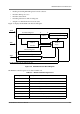

EOnCE Module Internal Architecture
SC140 DSP Core Reference Manual 4-19
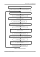
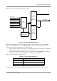
Figure 4-9 shows a block diagram of the event counter.
Figure 4-9. Event Counter Block Diagram
ECNT_VAL and ECNT_EXT are 32-bit registers, but their values are limited to 31 bits; their MSB is
always zero. Their range is from zero to $7FFF FFFF. The counter counts down, while the extension
counter counts up. The event counter has two counting modes:
• Single count: The counter counts down to zero, and then disables. Upon reaching zero, an EOnCE
event is generated (the outcome depends on the event selector).
• Extended count: When the counter reaches zero, it wraps around to $7FFF FFFF and continues to
count. The extension counter is incremented. No EOnCE event is generated.
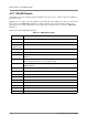
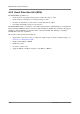
Table 4-7 shows the event counter register set.
The functionality of the event counter registers is described in Section 4.8, “Event Counter Registers.”
Table 4-7. Event Counter Register Set
Register Name Description
ECNT_CTRL Event counter control register
ECNT_VAL Event counter value register (32-bit)
ECNT_EXT Extension counter value register (32-bit)
Event
31-bit
Counter
ECNT_VAL
System Clock
Inst Execution
Event0-5
EventD
Trace
Count Event
Count
Selector
Control Register
DEBUGEV
ECNT_CTRL
Count Value
31-bit
Extension
ECNT_EXT
Counter
EC0-1
External EDCA6,7 event