
DSP Core Reference Manual


6-60 SC140 DSP Core Reference Manual
ISAP instructions and instruction encoding
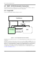
6.3 ISAP instructions and instruction encoding
This section presents an overview of the concept of programming the ISAP from the SC140 assembly
code.
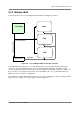
The SC140 core can dispatch one ISAP opcode per VLES. This opcode uses the 2-word prefix encoding,
and is recognized as an ISAP opcode if it is not the first opcode in the VLES. The SC140 core encoding
rules allow this situation only with prefix grouping, hence it follows that an ISAP opcode can only appear
as part of a prefixed VLES.
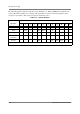
The 2-word prefix encoding is shown in Table 6-1: ISAP Encoding Fields below:
This encoding allows the ISAP 25 bits as its encoding space. The ISAP architect can freely allocate these
bits. The only constraint is that in case the ISAP is intended to be used as part of a multi-ISAP
configuration, some of the Most Significant Bits of the 25 bits should be reserved for ISAP selection
encoding. The number of such bits that are to be left aside is also the decision of the ISAP architect.
An ISAP opcode can specify one or more ISAP instructions. An ISAP could be defined as a VLIW
processor, encoding more than one instruction in one ISAP opcode.
ISAP instructions can be of two main kinds:
• ALU instructions: ISAP instructions that execute with a pipeline similar to the core DALU, without
activation of simultaneous core AGU instructions.
• Data move instructions: Instructions that transfer data between the ISAP and its environment
(external Data memory or SC140 core). The core has the capability of providing the ISAP with data
addressing, so that the ISAP designer need not incorporate an AGU in the ISAP. This requires certain
conventions, which are detailed in Section 6.4, “ISAP Memory Access,” .
ISAP instructions must obey the same VLES semantics as other SC140 instructions (dependency of
operands between VLES, etc.). At the instruction level, the syntax should be as close as possible to existing
SC140 conventions (source and destination order, data width specifiers, etc.). The individual ISAP
instruction syntax should be defined in the particular ISAP specification.
The term “ISAP instruction” can be used both to specify the assembly mnemonic, or to the specific
sub-opcode in the ISAP opcode related to the source mnemonic. Differentiation is according to context -
source code or assembly level context, or encoding context.
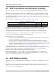
6.4 ISAP Memory Access
The ISAP accesses data via the XDBA and the XDBB busses, in addition to core-ISAP buses for register
transfer.
The ISAP should not be designed with an AGU, leaving the addressing duties to the core. This allows the
ISAP to enjoy the full addressing and modulo capabilities of the core AGU, and the ISAP design to
concentrate on the specific ISAP specialty.
Table 6-1. ISAP Encoding Fields
Binary Encoding Words Bits
0011 _ _ _ _ _ _ _ _ _ _ _ _ _ 101_ _ _ _ _ _ _ _ _ _ _ _ _ _ 2 25