
DSP Core Reference Manual


A-24 SC140 DSP Core Reference Manual
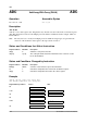
ADD
ADD Add (DALU) ADD
Description
These operations add two source operands and store the result in a destination data register (Dn).
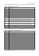
Status and Conditions that Affect Instruction
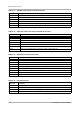
Status and Conditions Changed by Instruction
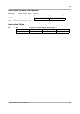
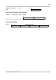
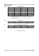
Example 1
add d0,d1,d2
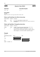
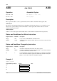
Operation Assembler Syntax
#u5 + Dn → Dn
ADD #u5,Dn {0 ≤ u5 < 32}
Da + Db → Dn
ADD Da,Db,Dn
ADD #u5,Dn
The five bits of the unsigned immediate are right-aligned and the upper bits are zero-extended to form a
40-bit source operand. That operand is then added to a data register (Dn) and the result stored in the
destination data register (Dn).
ADD Da,Db,Dn
Adds two source data registers (Da and Db) and stores the result in a destination data register (Dn).
Register Address Bit Name Description
SR[2] SM If set, selects 32-bit arithmetic saturation mode.
SR[5:4] S[1:0] Scaling mode bits determine which bits in the result are used in the Ln bit
calculation.
Register Address Bit Name Description
SR[0] C Calculates and updates the C bit in the status register.
EMR[2] DOVF Set if the result cannot be represented in 40 bits, or if the result saturates
to 32 bits in arithmetic saturation mode.
Ln L If not in arithmetic saturation mode (SR [SM] = 0), calculates and updates
the Ln bit in the destination register. If in arithmetic saturation mode (SR
[SM] = 1), clears the Ln bit in the destination register.
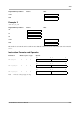
Register/Memory Address Before After
SR
$00E0 0000
D0
$00 0000 0005
D1
$00 0000 0002