
DSP Core Reference Manual


A-224 SC140 DSP Core Reference Manual
LSLL
LSLL Multiple-Bit Bitwise Shift Left (DALU) LSLL
Description
Status and Conditions that Affect Instruction
None.
Status and Conditions Changed by Instruction
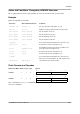
Example 1
lsll d4,d2
Operation Assembler Syntax
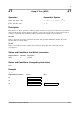
If Da[6:0] > 0, then Dn << Da[6:0] → Dn
else Dn >>> ⏐Da[6:0]⏐ → Dn
LSLL Da,Dn {–40 ≤ Da[6:0] ≤ 40}
LSLL Da,Dn
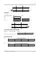
Logically shifts a 40-bit data register (Dn) left or right N bits. N is a signed 6-bit integer contained in
Da[6:0].
If N is positive, Dn is shifted left. Bit (40 – N) is stored in the C bit. Bits [(39 – N):0] are copied to bits
[39:N]. Bits [(N – 1):0] are cleared.
If N is negative, Dn is shifted right. Bit (|N| – 1) of Dn is stored in the C bit. Bits [39:|N|] are copied to bits
[(39 – |N|):0]. Bits [39:(40 – |N|)] are cleared.
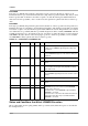
Register Address Bit Name Description
SR[0] C Bit (40 – N) of Dn is stored in the C bit for a left shift. Or, bit (|N| – 1)
of Dn is stored in the C bit for a right shift.
Ln L Clears the Ln bit in the destination register.
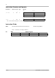
Register/Memory Address Before After
D4
$00 0000 0002
SR
$00E4 0000 $00E4 0001
L2:D2
$0:$FF 8765 4321 $0:$FE 1D95 0C84
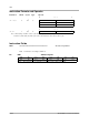
0
01516313239C
01516313239 C
Da[6:0] > 0
Da[6:0]
≤ 0
0