
DSP Core Reference Manual

2-38 SC140 DSP Core Reference Manual
Address Generation Unit
2.3.3 Addressing Modes
The SC140 core provides four types of addressing modes:
• Register direct
• Address register indirect
• PC relative
• Special
The addressing modes are related to where the operands are to be found and how the address calculations
are to be made. These modes are described in the following sections:
2.3.3.1 Register Direct Modes
The register direct addressing modes specify that the operand is in one or more of the DALU registers,
AGU registers, or control registers, and are classified as register references.
• Data or Control Register Direct — The operand is in one, two, or four DALU registers as specified
in a portion of the data bus movement field in the instruction. An example is: mac d4,d5,d6,
which uses data registers d4, d5, and d6 as sources for the multiply-accumulate operation. This
addressing mode is also used to specify a control register operand for special instructions.
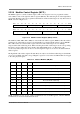
• Address Register Direct — The operand is in one of the twenty-seven AGU registers (R0–R7,
R8–R15/B0–B7, N0–N3, M0–M3, MCTL, N/ESP) specified by a field in the instruction. An
example is addl1a r0,r1, which performs a 1-bit arithmetic left shift on the data in R0, and adds the
result to the data in R1.
2.3.3.2 Address Register Indirect Modes
The address register indirect modes specify that the address register is used to point to a memory location.
The term indirect is used because the register contents are not the operand itself, but rather the operand
address. These addressing modes specify that an operand is in a memory location and specify the effective
address of that operand. These references are classified as memory references. The term “index” refers to
an offset stored in a register. The term “displacement” refers to an offset from an immediate in the
instruction.
• No Update, (Rn) — The operand address is in the address register. The contents of the address
register are unchanged by executing the instruction. For R0-R7, the contents of the modifier control
register (MCTL) are ignored. An example is: bmclr.w #$004f,(r4). A word is read from
memory location stored in r4, operated on, and written back to the same location. The address in r4
is unchanged.
• Post-increment, (Rn)+ — The operand address is in the address register. After the operand address
is used, it is incremented by the access width (1, 2, 4, or 8 bytes) and stored in the same address
register. The access width is the number of bytes used by the active instruction on the memory data
bus. Incrementing the operand address by the access width places the next available byte address in
the register. The type of arithmetic used for updating R0-R7 is determined by programming the
MCTL register. An example is: move.f (r3)+,d2. The data in the location identified by the
value in r3 is moved to data register d2. Then the value in r3 is incremented by two.