
DSP Core Reference Manual

2-60 SC140 DSP Core Reference Manual
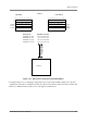
Memory Interface
2.4.1.4 Multi-Register Moves
For accesses involving more than one register, such as with MOVE.2W or MOVE.4F instructions, the
SC140 ensures that data originating from a specific register reaches the same address in memory in both
little and big endian modes (and the other way round). The memory system does not distinguish between
MOVE.L and MOVE.2W transfers that have the same data width. Memory treats them both like a long
word transfer. If the data bus were the same for both endian modes in a two-register transfer, the data from
the two registers would end up in different addresses. To correct for this, the byte order on the buses for
multi-register transfers is adjusted for the little endian mode. The memory also does not distinguish
between transfers of four words or two long words. It treats them both like a string of eight bytes. The bus
structure for the little endian mode corrects for both cases to ensure that register data is stored at the same
address for both modes.
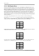
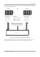
As an example of the problem that arises if a correction is not made, consider the following case:
The instruction move.2w d0:d1,(a8) transfers two integer words from data registers d0 and d1 to
memory at address a8. For d0 = $0102 and d1 = $0304, the data bus would be $01020304, and the memory
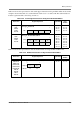
would be accessed for a width of 32 bits. For big endian mode, the memory would look like:
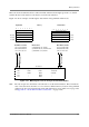
For little endian mode, the memory would be accessed for a width of 32 bits (like a long word), and then it
would write the data little end first such that the memory would look like:
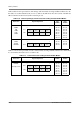
Note that the data word from d0, $0102, is at a different address for the two modes. If the data bus were
modified by the core to $03040102, then the memory for little endian mode would look like:
Address Data
a8 01
a9 02
a10 03
a11 04
Address Data
a8 04
a9 03
a10 02
a11 01
Address Data
a8 02
a9 01
a10 04
a11 03