
DSP Core Reference Manual

Memory Interface
SC140 DSP Core Reference Manual 2-61
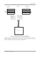
This is the desired result. This effect is achieved in little endian mode through logic in the core, which
modifies the data on the data bus to the memory for both reads and writes.
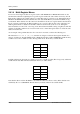
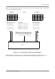
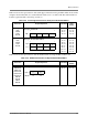
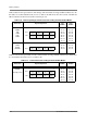
Figure 2-23 shows examples of multi-register data transfers in big and little endian modes.
Figure 2-23. Multi-Register Transfer in Big and Little Endian Modes
Note: The only exceptions to the behavior described above are the VSL instructions. These instructions
cause source data words from the core to be written to different memory locations in big and little
endian modes. For more information about the VSL instructions, refer to Table 2-27 on page 2-64,
and Appendix A, “Viterbi Shift Left Move (AGU) VSL,” on page A-422..
Big Endian
Little Endian
(a) MOVE.2W (A8), D0:D1
(b) MOVE.4W (A8), D0:D1:D2:D3
(c) MOVE.2L (A16), D0:D1
64-bit XB-BUS
64-bit XA-BUS
xxxx xxxx 0102 0304
0102 0304 0506 0708
1122 3344 ccdd eeff
xxxx xxxx 0304 0102
0708 0506 0304 0102
ccdd eeff 1122 3344
InstructionsData Bus Contents Data Bus Contents
64-bit XB-BUS
64-bit XA-BUS
SC140
Core
Memory
(a) (b) (c)
D0
D1
D2
D3
0102
0304
–
–
0102
0304
0506
0708
11223344
ccddeeff
–
–
0
8
16 ($10)
24 ($18)
32 ($20)
76543210
0f 0e 0d 0c 0b 0a
07 08 05 06 03 04 01 02
cc dd ee ff 11 22 33 44
8
16 ($10)
24 ($18)
32 ($20)
01234567
0
0a 0b 0c 0d 0e 0f
01 02 03 04 05 06 07 08
11 22 33 44 cc dd ee ff