
DSP Core Reference Manual

2-64 SC140 DSP Core Reference Manual
Memory Interface
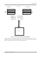
2.4.1.6 Memory Access Behavior in Big/Little Endian Modes
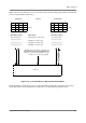
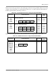
Table 2-27 shows the representation of the move instructions in big and little endian modes. In the
examples shown in this table, it is assumed that R0 points to address A0. Each alphanumeric A–H
represents one byte. Also, the memory contents may not exactly equal the register contents. For example,
in VSL instructions, the memory word (16 bits) is the register word shifted left by one bit. See Appendix A
for more detailed information.
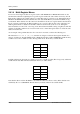
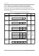
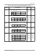
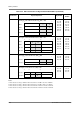
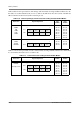
Table 2-27. Move Instructions in Big and Little Endian Modes
Instruction Register Operands Big Endian
Little
Endian
MOVE.B
MOVEU.B
A0 = A A0 = A
MOVE.W
MOVEU.W
A0 = A
A1 = B
A0 = B
A1 = A
MOVE.2W A0 = A
A1 = B
A2 = C
A3 = D
A0 = B
A1 = A
A2 = D
A3 = C
MOVE.4W A0 = A
A1 = B
A2 = C
A3 = D
A4 = E
A5 = F
A6 = G
A7 = H
A0 = B
A1 = A
A2 = D
A3 = C
A4 = F
A5 = E
A6 = H
A7 = G
MOVE.L
MOVEU.L
MOVES.L
A0 = A
A1 = B
A2 = C
A3 = D
A0 = D
A1 = C
A2 = B
A3 = A
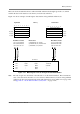
039 8
A
D0 =
Examp
l
e: M
O
VE.B D
0
,
(
R
0)
039
16
A
B
Example: MOVE.W D0, (R0)
D0 =
039 16
AB
CD
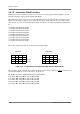
Example: MOVE.2W D0:D1, (R0)
D0 =
D1 =
039
16
AB
CD
EF
GH
Example: MOVE.4W D0:D1:D2:D3, (R0)
D0 =
D1 =
D2 =
D3 =
039 32
AB
C
D
Example: MOVE.L D0, (R0)
D0 =