
Reference Manual
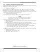


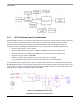


Table Of Contents

USB-KW24D512
USB-KW2x Hardware Reference Manual, Rev. 0.1
3-6 Freescale Semiconductor
Figure 3-6. USB-KW24D512 Power Management Circuit
The USB-KW24D512 is powered via the USB type A connector as shown in Figure 3-6.,
“USB-KW24D512 Power Management Circuit”; the MKW24D512 device has an on-board USB port
which is configured to provide both power and serial communication with the target MCU.
3.2.4 USB-KW24D512 Peripheral Functions
The USB-KW24D512 includes two switch buttons; one for general purpose peripheral function to assist
in implementing targeted applications and the other is for board hardware Reset.
In the same situation the USB-KW24D512 includes two LEDs for general purpose peripheral function to
assist on applications.