
User's Manual


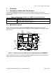


Table Of Contents
- General Description
- Features
- Evaluation Kit Applications
- Revision Table
- Table of Contents
- List of Figures
- List of Tables
- Overview
- Installation and Setup
- Configuring Evaluation Kit Hardware
- Evaluation Kit Hardware Description
- PHY Evaluation Using the Wireless Developer Kit
- Summary List of Test Hardware and Software Required
- Equipment Handling
- Guidelines for Running Tests
- Transmit Spectral Mask Compliance Test
- Total Average Transmit Power Test
- Peak Envelope Power Test
- Receiver Sensitivity and Scaled Ranged Versus Throughput Tes
- Receiver Immunity Test
- Minimum Antenna Separation Test
- Penetration Test
- Video Transmission and Reception
- Operating Conditions and Characteristics
- Support
- FCC Compliance Statement
- License Agreement
- Warranty Disclaimer
- Glossary
- References
- Appendix A – Sources for Leasing of Test Equipment
Rev 1.4, June 2, 2004, June 2, 2004 Page 6 of 44 Page 6
o
List of Figures
Figure 1: Top Side Layout of UWB Transceiver Model Number XSUWBWDK ............................7
Figure 2: Bottom Side Layout of UWB Transceiver Model Number XSUWBWDK .......................8
Figure 3: Wireless Developer Kit Logical Block Diagram............................................................12
Figure 4: Antenna Gain Versus Frequency.................................................................................15
Figure 5: Equipment Setup for Transmit Spectral Mask Compliance Test .................................19
Figure 6: Equipment Setup for the Total Average Transmit Power Test.....................................23
Figure 7: Equipment Setup for the Peak Envelope Power Test..................................................24
Figure 8: Setup for the Receiver Sensitivity, Scaled Range Versus Throughput and Receiver
Immunity Tests....................................................................................................................26
Figure 9: Setup for Minimum Antenna Separation Test..............................................................37
Figure 10: Setup for Penetration Test.........................................................................................38
Figure 11: Setup for Video Transmission....................................................................................39
List of Tables
Table 1: Motorola Part Numbers for UWB Development Hardware..............................................7
Table 2: Summary of MC270141 Firmware Ugrade Files...........................................................11
Table 3: Summary List of Equipment for Motorola UWB RF Measurements..............................16
Table 4: Transmit Frequencies of Common Devices in the UWB Frequency Range .................36
Table 5: Consumer Electronics Devices that Operate with Motorola UWB Transceivers..........40
Table 6: Definitions for Terms, Abbreviations and Acronyms Used............................................42