
User's Manual


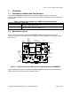


Table Of Contents
- General Description
- Features
- Evaluation Kit Applications
- Revision Table
- Table of Contents
- List of Figures
- List of Tables
- Overview
- Installation and Setup
- Configuring Evaluation Kit Hardware
- Evaluation Kit Hardware Description
- PHY Evaluation Using the Wireless Developer Kit
- Summary List of Test Hardware and Software Required
- Equipment Handling
- Guidelines for Running Tests
- Transmit Spectral Mask Compliance Test
- Total Average Transmit Power Test
- Peak Envelope Power Test
- Receiver Sensitivity and Scaled Ranged Versus Throughput Tes
- Receiver Immunity Test
- Minimum Antenna Separation Test
- Penetration Test
- Video Transmission and Reception
- Operating Conditions and Characteristics
- Support
- FCC Compliance Statement
- License Agreement
- Warranty Disclaimer
- Glossary
- References
- Appendix A – Sources for Leasing of Test Equipment

Rev 1.34, June 2, 2004
Copyright © 2001-2004 Motorola, Inc. All rights reserved. Page 8 of 44
Power
LED
JTAG
Connector
Reverse
SMA
Connectors
1394
Connectors
RS232
Port
Reserved
Connector
Figure 2: Bottom Side Layout of UWB Transceiver Model Number XSUWBWDK
1.3. Applicability of This Manual
This WDK Hardware Guide is intended for use with:
• UWB transceivers having a model number of XSUWBWDK.
• Version 2.0 or later of the Motorola XtremeSpectrum Software Development Kit.
2. Installation and Setup
2.1. Items Supplied by Motorola
A single Wireless Developer Kit contains the following items:
• Two model XSUWBWDK UWB transceivers in metal enclosures.
• Four UWB antennas.
• Four semi-flexible coaxial cables for connection of the Motorola antenna to a UWB
transceiver.
• Two +5 VDC power supplies that accept 110 – 240 VAC input.
• Two IEEE1394 cables, each with four pin connectors on the ends.
• An SDK CDROM.. For the content of this CDROM, see the XtremeSpectrum Software
• Motorola UWB Software Development Kit Utilities Guide.
• A special cable for updating firmware used by the MC270141 MAC internal to the
Evaluation Kit. This ByteBlaster
TM
cable is manufactured by Altera Corporation. Note that
this cable is supplied only to customers who have not received one previously from
Motorola.
The minimum, and default, system configuration shipped by Motorola consists of two UWB
transceivers. Additional transceivers can be purchased to form a multi-point configuration. Setup
and use of such a configuration is covered in more detail in section 3.
Note: The expression “Wireless Developer Kit”, or WDK, refers to the complete set of
hardware and software deliverables from Motorola. The expression “Software