
Reference Manual
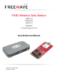
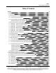

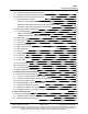
Table Of Contents
- Preface
- 1. Introduction
- 2. Basic Radio Programming and Setup
- 2.1. Setting the Radio's Role in the Network and the Network Type
- 2.2. Establishing Communication with Instrumentation and Computers
- 2.3. Establishing Communication with Other Radios in the Network
- 2.4. Designate the RF Transmission Characteristics
- 2.4.1. 900MHz Channel Select Parameters
- 2.4.2. 900MHz Frequency Key (Golden Setting)
- 2.4.3. 900MHz Frequency Zones
- 2.4.4. High Noise
- 2.4.5. 900MHz Hop Frequency Offset
- 2.4.6. 900MHz Hop Table Size
- 2.4.7. 900MHz Hop Table Version
- 2.4.8. Max Packet Size and Min Packet Size (Golden Setting)
- 2.4.9. MCU Speed
- 2.4.10. Remote LED
- 2.4.11. Retry Time Out
- 2.4.12. RF Data Rate (Golden Setting)
- 2.4.13. RTS to CTS
- 2.4.14. Slave Security
- 2.4.15. Transmit Power
- 2.4.16. Transmit Rate
- 3. Configuring Point-to-MultiPoint Networks
- 3.1. Point to MultiPoint Network Characteristics
- 3.2. Point-to-MultiPoint Network Quick Start
- 3.3. Point-to-MultiPoint Operation LEDs
- 3.4. Overlapping MultiPoint Networks
- 3.5. Establishing Communication with Other Radios in a MultiPoint Network
- 3.6. Routing Communications through the Network
- 3.7. Setting Other MultiPoint Parameters
- 3.7.1. 1 PPS Enable Delay
- 3.7.2. Diagnostics
- 3.7.3. DTR Connect
- 3.7.4. Local Mode
- 3.7.5. Master Packet Repeat
- 3.7.6. Master Packet Repeat in MultiPoint Networks with Repeaters
- 3.7.7. Max Slave Retry
- 3.7.8. Radio ID
- 3.7.9. Radio Name
- 3.7.10. Repeaters
- 3.7.11. Repeater Frequency
- 3.7.12. Retry Odds
- 3.7.13. Slave / Repeater
- 3.8. Conserving Power
- 3.9. Reading Diagnostics in Tool Suite
- 4. Configuring Point-to-Point Networks
- 5. Advanced Programming
- 6. Viewing Radio Statistics
- 7. Approved Antennas
- 8. FGR3 Wireless Data Radios Pinouts
- 9. Troubleshooting
- 10. FGR3 Release Notes
- Appendix A: FGR3 Technical Specifications
- Appendix B: FGR3 Board Level Mechanical Drawing
- Appendix C: 900MHz Factory Default Settings
- Appendix D: 900MHz Channel Frequency IDs
- Appendix E: FreeWave Legal Information

FGR3
User-Reference Manual
LUM0110AA Rev Jan-2019 Page 6 of 143 Copyright © 2019FreeWave
This document is subject to change without notice. This document is the property of FreeWave Technologies, Inc.
and contains proprietary information owned by FreeWave. This document cannot be reproduced in whole or in
part by any means without written permission from FreeWave Technologies, Inc.
5.2. Setting and Changing Radio Passwords 100
5.2.1. Setting the Password 100
5.2.2. Changing a Password 100
5.2.3. Disable a Password 101
5.3. Enable and Set Up AES Encryption 101
5.3.1. Encryption Channel Key 102
5.3.2. Encryption Key 103
5.3.3. Encryption (Strength) 104
5.3.4. Troubleshooting AES Setup 105
5.4. Low Baud Rates 106
5.5. Multi-Master Sync 106
5.6. Time Divisible Multiple Access (TDMA) 106
6. Viewing Radio Statistics 107
6.1. View Statistics in Tool Suite 108
6.2. View the Radio Transmission Characteristics in the Terminal Interface 108
6.2.1. Antenna Reflected Power 108
6.2.2. Master-Slave Distance 108
6.2.3. Noise Level 108
6.2.4. Number of Disconnects 109
6.2.5. Radio Temperature 109
6.2.6. Rate % (Receive Percentage Rate) 109
6.2.7. Signal Level 110
6.2.8. Transmit Current 110
7. Approved Antennas 111
7.1. 900MHz Yagi Directional Antennas 112
7.2. 900MHz Omni-directional Antennas 112
8. FGR3 Wireless Data Radios Pinouts 113
8.1. Operational RS422 and RS485 Information 113
8.2. Pinout Assignments and Descriptions 113
8.3. 20-Pin Diagnostics Connector Pinout 114
8.4. RF Board Level Pinout 115
8.5. RS-232 Pin Assignments (DB-9) 116
8.6. RS422 and RS485 Full Duplex Pinouts 116
8.7. RS485 Half Duplex Pinouts 117
8.8. Waterproof Enclosure Pinout 118
9. Troubleshooting 119
9.1. Troubleshooting Flowchart 120
9.2. General Troubleshooting 120
9.3. Unlicensed Serial Radio - Specific Troubleshooting 123