Boost Charger ™ DC Fast Charging Station Installation Guide Version 1.
Copyright and trademarks ©2014-2020 FreeWire Technologies, Inc. All rights reserved. This material is protected by the copyright laws of the United States and other countries. It may not be modified, reproduced or distributed without the prior, express written consent of FreeWire Technologies, Inc. FREEWIRE, FREEWIRE TECHNOLOGIES, AMP and BOOST CHARGER are U.S. registered trademarks and service marks of FreeWire Technologies, Inc. and cannot be used without the prior written consent of FreeWire®.
Safety and compliance The FreeWire Boost Charger is for Outdoor Use Only and to be mounted on a non-combustible surface such as a concrete pad that extends a minimum of 3 feet beyond the perimeter of the battery system/Boost Charger. The Boost Charger should comply with all local and national codes and standards and only be installed by a licensed contractor and a licensed electrician. It is the site owner’s responsibility to comply with all local codes and safety laws.
Boost Charger DC Fast Charging Station Installation Guide Version 1.0 Table of Contents BEFORE YOU START................................................................................................................................... 6 GENERAL WARNINGS................................................................................................................................ 7 SAFETY SHUTDOWN................................................................................................................
Powering on the Boost Charger............................................................................................................................. 29 Commissioning the Boost Charger....................................................................................................................... 30 Complete a Test Charging Session....................................................................................................................... 30 3 BOOST CHARGER SPECIFICATIONS.............
BEFORE YOU START This guide contains important instructions that must be followed to ensure safe installation of the FreeWire Boost Charger® DC fast charging station. Be sure to complete the steps outlined in the Boost Charger Site Preparation Guide (770-00004-01) prior to installing the Boost Charger.
General Warnings SHOCK RISK: HIGH VOLTAGE ELECTRICITY WARNING: To reduce the risk of injury, read all instructions and caution markings before installing the FreeWire Boost Charger. WARNING: The FreeWire Boost Charger must be installed by licensed technicians and in accordance with all instructions. WARNING: Installation must be done in accordance with all local electrical codes and/or the National Electrical Code® (NEC®).
1 OVERVIEW 1 Overview To ensure the successful installation of the FreeWire Boost Charger® DC fast charging station, please be sure to read this overview and become familiar with the Boost Charger and the necessary tools and equipment to install it. NOTE: The FreeWire Boost Charger must be installed by a licensed contractor and a licensed electrician.
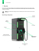
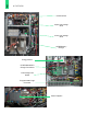
1 OVERVIEW Boost Charger Main Component Overview Circuit Breakers Internet Connection (optional) Remote e-Stop Connection Grid AC Connections Ground Connection Heat Exchanger DC/DC Converters Circulating Pump Battery Cooler/ HVAC Battery Stack 9
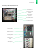
1 OVERVIEW Contactor Box Upper Low-Voltage Shelf Lower Low-Voltage Shelf AC/DC Battery Charger Energy Meters CCS/CHAdeMO EV Charger Controllers Low Voltage Fuse Board Programmable Logic Controller Power Supplies 10
1 OVERVIEW Low Voltage Battery Battery Management System Cellular Modem Computer Processor Circuit Breakers Breaker Function 1 Main AC contactor 2 AC/DC battery charger 1 3 AC/DC battery charger 2 4 Battery air conditioning 5 Liquid cooling system pump 6 24 V system power supply 8 Computer processor power 9 Battery heaters 1 2 3 4 5 8 Located on the upper low-voltage shelf 11 6 9
1 OVERVIEW Unlocking and Locking the Front Access Door In order to unlock/lock the Boost Charger front access door, the locks behind the CHAdeMO and CCS charge cables must be accessible. Step 1 Remove the CHAdeMO charge cable from its respective holder. Step 2 Insert the key and turn to unlock. Step 3 Remove the key. Step 4 Insert the door tool and pull open the hasp. Step 5 Remove the door tool. Step 6 Repeat steps 1-5 for the second lock behind the CCS charge cable.
1 OVERVIEW Installation Overview Installing the FreeWire Boost Charger requires three people and takes approximately two hours. The following steps are required for installation: Step 1 Schedule commissioning a week prior to installation. Please reference the section titled ‘Commissioning the Boost Charger’ in section 2. Step 2 Confirm that the site is ready per the Boost Charger Site Preparation Guide, and all required equipment and tools are available.
1 OVERVIEW Preparation Before beginning the installation: 1. Check that the concrete pad is level and cured. 2. Verify that the service wiring, circuit protection, and metering complies with local codes/regulations and is ready per the Boost Charger Site Preparation Guide (Part Number 770-00004-01) 3. Ensure the grounding conductor is properly grounded and complies with local codes. 4. Confirm there is a strong cellular signal available. The Boost Charger requires a cellular network.
1 OVERVIEW Boost Charger Crate Packing List • Boost Charger • Door access keys (2x) • Door Tool Boost Charger Overall Dimensions 15
1 OVERVIEW Equipment Needed • Forklift (5,000lb capacity minimum) or crane (5,000lb capacity minimum) with nylon lifting straps and four-point lifting sling • Forklift tyne extensions (as required) • 15/16” wrench and socket • #2 Phillips screwdriver • T27 tamper proof pin-in Torx driver and bit • 15/16” Crows foot wrench • Torque wrench (200 ft-lbs) • Torque wrench (100 in-lbs) • 2 AWG lug (grounding the service wire and earth ground) • Zip ties (as necessary) • Standard electrical eq
2 INSTALLATION OF THE BOOST CHARGER 2 Installation of the Boost Charger The steps outlined in this procedure require the use of a forklift or crane to lift, move, and mount the Boost Charger. A crane setup using a four-point sling, similar to the example pictured to the right, may be used in situations when a forklift cannot be used for installation. It is recommended that the crane and four-point sling are certified and capable of carrying at least 5,000 lbs.
2 INSTALLATION OF THE BOOST CHARGER Uncrating the Boost Charger Step 1 Lift the crate using a forklift or crane and place it vertically on level ground in front of the installation pad. Warning: Due to the size and weight of the Boost Charger, care should be taken when lifting to prevent tipping. Note: If a wall is located behind the installation pad, ensure the forklift tynes don’t protrude too far that they hit the wall when moving the Boost Charger onto the pad.
2 INSTALLATION OF THE BOOST CHARGER Step 3 Remove the bolts from the side panel. Step 4 Release the six side and two top hasps which are used to hold the side panel of the shipping crate.
2 INSTALLATION OF THE BOOST CHARGER Step 5 Using two people, carefully remove the side panel from the shipping crate as shown. Step 6 Using two people, carefully slide the remaining four panel structure away from the Boost Charger.
2 INSTALLATION OF THE BOOST CHARGER Step 7 Carefully cut metal bands from the Boost Charger using a band cutter. Step 8 Carefully remove the protective plastic from the Boost Charger.
2 INSTALLATION OF THE BOOST CHARGER Step 9 Remove the four screws that hold in the front and backside kick panels using a pin-in-torx bit. Set the hardware aside for future use. Step 10 Remove both the front and backside kick panels and set them aside for re-installation later.
2 INSTALLATION OF THE BOOST CHARGER Step 11 Remove the four bolts which secure the Boost Charger to the shipping base using a 15/16 inch socket wrench. Step 12 Using a forklift or crane, carefully lift the Boost Charger from the base of the crate and station it at the concrete foundation pad for installation.
2 INSTALLATION OF THE BOOST CHARGER Mounting the Boost Charger Step 1 Remove the cap from each of the 8 mounting bolts on the concrete installation pad. Concrete Pad Protective Caps (x8) Mounting Bolts (x8) Conduit Step 2 Using a forklift or crane, slowly lift the Boost Charger over the eight mounting bolts on the installation pad, ensuring the bolts align with the corresponding holes in the bottom mounting beams, then lower the Boost Charger over the bolts.
2 INSTALLATION OF THE BOOST CHARGER Step 3 Use the washers and locking nuts supplied with the mounting template to install the Boost Charger. Insert a flat washer, then thread a locking nut onto each of the eight mounting bolts to secure the unit. Step 4 Ensure you have room to maneuver around the Boost Charger. Step 5 Tighten the outer 4 nuts first. Then tighten the center front and back nuts by hand-turning the lower nuts until they are flush against the Boost Charger frame.
2 INSTALLATION OF THE BOOST CHARGER Step 7 Torque the bolts to 70 +/- 10 in-lbs. Grounding Requirements The FreeWire Boost Charger must be grounded. Use a grounded, metal, permanent wiring system that runs with circuit conductors and connects to the charger equipment ground on the Boost Charger. An earth ground that complies to local codes must also be used for the Boost Charger. Check the Site Preparation Guide for details.
2 INSTALLATION OF THE BOOST CHARGER Step 1 Boost Charger works with a normally closed external safety shutoff switch. In order to wire up the external safety shutoff switch, the red jumper shown below must first be removed. Step 2 Wire up the remote shut off using 20 AWG wire as shown below. Step 3 Be sure to test the operation of the external safety switch per local codes and regulations before putting into use.
2 INSTALLATION OF THE BOOST CHARGER Connecting Electrical Power Step 1 Once the Boost Charger has been bolted to the concrete pad and torqued, open the front access door of the charger using the provided keys. Step 2 Prepare the service wiring by making sure it has been pulled through the conduit to the installation pad. Note: The terminal block on the Boost Charger accepts 2 AWG wires only. If using a larger gauge wire to accommodate a long run, reduce the wire size at the disconnect.
2 INSTALLATION OF THE BOOST CHARGER Step 9 Bundle the wires together using cable ties as necessary. Step 10 Verify that the Boost Charger breakers are on. Step 11 Seal the conduit openings using duct seal. Step 12 Close the front access door of the Boost Charger and lock it using the provided keys. Step 13 Unwrap the cable connectors and insert each connector into its corresponding holster. Important: You have now completed the physical installation of the Boost Charger.
2 INSTALLATION OF THE BOOST CHARGER Commissioning the Boost Charger The FreeWire Boost Charger uses EV Connect to allow drivers to easily find, access, and securely pay for EV charging. Drivers can search for and locate electric vehicle charging stations based on location, station ID, availability, power level provided, and accessibility. Before charging can begin, the Boost Charger fast charging station must be commissioned.
2 INSTALLATION OF THE BOOST CHARGER Step 4 Stop the charging session and return the connector to the holster. If the Boost Charger operates correctly and no errors exist, the installation is complete. If the Boost Charger does not power up, or fails to begin a charging session, confirm that the wiring is properly connected. If the Boost Charger is properly wired, but is not operating correctly, contact FreeWire support at support@freewiretech.com or 415-484-9590 for assistance.
3 BOOST CHARGER SPECIFICATIONS 3 Boost Charger Specifications System Max Output Power CHAdeMO: 100 kW CCS: 120 kW Combined: charge two vehicles up to 60 kW each Max Output Current CHAdeMO: 200 A CCS: 300 A Dimensions 40 in x 43 in x 96 in Weight 3,800 lbs Output Voltage, Charging 200 VDC – 500 VDC Electrical Input Input Rating 240 (+/- 10%) VAC, split-phase, 4-Wire, 120 A, 60 Hz 208 (+/- 10%) VAC 3-phase, WYE, 5-Wire, 80 A 60 Hz Wiring For 240 V - 2 conductors (L1, L2) Ground For 208 V - 4
NOTES Safety and Compliance Safety Compliance U.S.: complies with UL 2202, UL 2231-1, UL 2231-2, UL 991, UL 1973 (battery pack) EMC Compliance U.S.: FCC part 15 Class A Safety: Electric Vehicle • See the EV supplier’s guide for proper care of the EV and follow directions carefully. Failure to follow EV care instructions can results in EV explosion and property damage, severe injury, or death during charging. • Do not disconnect charger connector while the EV is charging.
www.freewiretech.com Any additional questions please contact: (415) 484-9590 support@freewiretech.com 1933 Davis St. Suite 301A San Leandro, CA 94577 Boost Charger Installation Guide v1.0. 8.24.