GlobalGuard Alarm System HISK1 Hardware Installation and Operating Manual 1
FOREWORD All devices in this wireless Alarm System are designed and manufactured to provide long reliable service. The system is designed for ease of installation using only conventional domestic tools. However, it is essential that the installer reads and fully understands the advice and procedures contained in this manual and plans the system before proceeding with the installation. Tools and Equipment Required: No.0 Philips Screwdrivers Bradawl No.1 Philips Screwdrivers Drill No.
physical protection such as security window and door locks. All units in the system are encoded to operate together using an 20 bit rolling House Code. The system House Code is automatically changed each time the system is armed/disarmed or triggered by a detector. The system can be operated from one or more accessory Remote Control Units and/or Keypads. It can also be operated remotely over the internet using a PC or mobile device(Android/Apple IOS device).
Gateway otherwise the software will not run correctly. If using a WIFI connection, ensure the PC is within operating range of the router. SECURITY DEVICES BACKWARD COMPATIBILITY Please note that earlier versions of the Response branded 868MHz security PIR movement detectors, magnetic door/window contact detectors, remote control and remote keypad devices are also compatible with this system.
PASSIVE INFRA-RED (PIR) MOVEMENT DETECTOR 20 CONTENTS KIT CONTENTS 7 INTRODUCTION AND OVERVIEW 8 Multiple Users User Access PIN Code System Arming Entry/Exit Delay Zones Zone Lockout Quick Set Event Log Chime Tamper Protection Jamming Detection Battery Monitoring Home Automation PLANNING AND EXTENDING 8 8 8 8 9 9 9 9 10 10 10 10 10 11 YOUR ALARM SYSTEM EXTERNAL SOLAR SIREN Configuring the Solar Siren Charging the Solar Siren Battery CONTROL PANEL Positioning the Control Panel Control Panel Overview
Device Remote Access Control Home Automation/Remote Sensor Learning a transmitter 59 60 60 Communication Device Setup 61 DEFAULT SETTINGS 39 RESET 41 PROGRAMMING 42 User Setup 42 Learn Remote Control 44 device 61 System Setup 46 Backup & Restore 62 Internal Siren Alarm Duration Wireless Siren Night Alarm Warning/Error Beep Jamming Detection Alarm Relay Zone Lockout Part-Arm I Setup Part-Arm II Setup Fully Arm Setup Holiday Arm Setup Date and Time Setup Learn Wireless Keypad Link Panel To
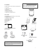
Please visit www.GlobalGuard.Friedland.co.uk to view an online installation video. Further details on setup and operation can be found in both this and the online software manual KIT CONTENTS The Alarm System should contain the following devices 1 x Solar Siren 1 x LCD Control Panel 1 x IP Gateway 1 x Wireless USB Dongle 1 x PIR Movement Detector 1 x Magnetic Door /Window Detector Also included: 1 x 12VDC Power Supply Adaptor (For Control Panel and charging Siren) 1 x 5VDC Power Supply Adaptor 1 x 0.
INTRODUCTION AND OVERVIEW left un-occupied, the ‘Fully Arm’ mode will arm all zones to protect the entire property, (i.e. upper and lower floors and outbuildings). MULTIPLE USERS The system allows for up to 8 Users, a Master (Admin) and 7 Users to be configured. This allows the system Event Log to maintain a record of which users have armed and disarmed the system. Each user will have a different User Access PIN Code.
typically installed at entry/exit points of your property. The system Exit-Delay may be configured for between 10 to 250 seconds or disabled completely. If a detector on a zone with its Entry-Delay enabled is triggered, then an alarm will not sound until the Entry-Delay period has expired. This allows time for the user to re-enter the property and disarm the system before an alarm occurs. Generally only the zones on the main entry route to the property will be configured with an Entry-Delay.
This enables the user to see which user has Armed/Disarmed the system and if and when any alarms occurred. The time, date and details of the event type will be recorded for each system event. CHIME Chime is a low security facility for use when the system is in Standby mode. If the Chime feature is ON, and a detector on a zone that has its Chime function enabled is triggered, the internal sounder will produce a low volume warning tone.
This hardware manual will only detail how to link these devices to the Control Panel. To operate these devices with a Programme, Schedule or Event, please refer to the online software manual available at www.GlobalGuard.Friedland.co.uk. PLANNING AND EXTENDING YOUR ALARM SYSTEM Before attempting to install your Alarm System it is important to study your security requirements and plan your installation accordingly. PIR Movement Detectors are used to protect the main areas of the property, (e.g.
Typical Installation using only the detectors supplied: 1. Place the 1st Door/Window Detector (configured on zone 1) on the front door. 2. Place a 2nd Door/Window Detector (configured on zone 2) on the back or patio doors. 3.
b. Any detectors covering the remainder of the lower floor apart from the entry/exit points (zones1&2) should be left with an instant delay (default for all other zones) for maximum security. c. Any detectors placed upstairs (which are not required when activating Part-Arm-I mode) should not be setup with Part-Arm I ON. Typical basic installations: ● ● ● ● ● Detectors on zones 1 and 2 will have a 30 second entry delay period. Detectors on all other zones are configured as INSTANT, (i.e.
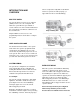
EXTERNAL SOLAR SIREN The Siren is encapsulated within a tough polycarbonate housing that also provides full protection against adverse weather conditions. An LED indicator unit is built into the Siren to act as a visible deterrent and indication that the system is active. The LEDs will slowly and alternately flash whether the system is Armed or Disarmed. When an alarm occurs the LEDs will flash rapidly together.
Under the cover you will also find a row of 5 DIP Switches labeled SW3 and a “LEARN” button. 1. Ensure that DIP Switch5 of SW3 on the LED indicator board is set to OFF (“SIREN”) for use with this alarm system. CHARGING THE SOLAR SIREN BATTERY Before getting your system up and running, it is important to initially charge up the battery for the Solar Siren for approximately 4 hours. 1. Remove the rear battery cover as shown below. 2.
CONTROL PANEL Note that to fully install the Control Panel in position, the siren’s battery charging process must be complete. If it has not yet completed then you should prepare mounting the Control Panel’s mounting bracket in position as described below. POSITIONING THE CONTROL PANEL When choosing a suitable location for the Control Panel, the following points should be considered. 1. 2. The Control Panel must be located within reach of a mains socket. 6.
The function keys I/II/III are home automation keys used to operate Programmes setup in the PC setup software INSTALLING THE CONTROL PANEL 1. Pull the clip outwards together with pushing the mounting bracket downwards to detach it from the rear of the Control Panel. 4. Ensure that the Reset jumper link (P1) and External Tamper Switch Jumper (P51) are set in the OFF position Terminal Block DC Jack Battery Connector P51: External Tamper P1: Reset 2.
IMPORTANT: The keys must be pressed firmly and within 5 seconds. If you make a mistake, press the “ESC” button and start the sequence again. so, again it is advisable to wear ear defenders as the tamper alarm will sound. 5. Connect the connector of the 7.2V NiMH rechargeable battery pack to the connector in the battery compartment. 6. Connect the plug of the 12V power adaptor to the DC jack in the panel. Route the cable along the cable track. 8.
The internet connection must be free from any firewalls/restrictions that might prevent remote access. INSTALLING THE IP GATEWAY 1. Connect the IP Gateway to a spare LAN port on your home broadband router as shown below: LINKING AN IP GATEWAY TO THE CONTROL PANEL (OPTIONAL) The gateway supplied in this kit has been supplied pre-linked to the Control Panel at the factory therefore you do not need to repeat this.
PASSIVE INFRA-RED (PIR) MOVEMENT DETECTOR Link push button DELETING THE IP GATEWAY FROM THE CONTROL PANEL (OPTIONAL) With the Control Panel in standby mode, enter programming mode by pressing the following keys: User access PIN code Use the and buttons to scroll through the menu until ‘5. Comms’ is displayed and press displayed. . ‘5-1 Comms Device’ will be Press the enter button again and ‘Input (01-12) Device NO.’ will be displayed.
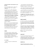
POSITIONING THE PIR DETECTORS The recommended position for a PIR Movement Detector is in the corner of a room mounted at a height between 2 and 2.5 metres. At this height, the detector will have a maximum range of up to 12 metres with a field of view of 110°. 7. Do not fix the PIR Detector onto or very close to metalwork (i.e. radiators, water pipes, etc) as this could affect the radio range of the device.
3. Use the rear cover as a template and mark the positions of the fixing holes on the wall. Fix the rear cover to the wall using the two 18mm No.4 screws and 22mm wall plugs, (a 5mm hole will be required for the wall plugs). Do not over-tighten the screws as this may distort or damage the cover. until the PIR has stabilized. Then the LED will stop flashing and turn OFF.
On initial installation the detector should be configured into Walk Test ready for testing, (i.e. Pressing down SW1 for 2s). 2. Scroll through the programming menu until ‘3. Security Sensor Zone’ is displayed and press . ‘3-1 Wireless Sensor Zone’ will be displayed. 6. Refit the PIR Detector to the rear cover by offering the detector up to the rear cover and locate the clips in the top edge into the rear cover.
If the detector is new and not already linked on any security zone the panel will produce two short beeps and the display will show ‘New Device’ 6. 2. Use the and buttons to scroll through the menu until ‘Detector Walk Test’ is displayed and press Confirm the new device ID code by activating the Tamper Switch on the same new PIR detector within 15s. . Walk Test Note: If the confirmation signal is not received within 15s the control panel will produce a single long beep and exit the learning process.
IMPORTANT: In normal operation, the LED indicator behind the detector lens will not flash on movement detection, (unless the battery is low). When the detector is fully installed i.e. battery cover fitted and in operating mode; in order to conserve power and maximize battery life the PIR Detector will only detect movement if there has been no movement detected within the previous 2 minutes. MAGNETIC DOOR/ WINDOW CONTACT DETECTORS The Magnetic Contact Set comprises of two parts; a Detector and a Magnet.
2. The Detector and Magnet should be mounted together along the opening edge of the Window/Door opposite the hinges. Ensure that the parallel gap between the Magnet and Detector is less than 10mm and that the arrow on the magnet is aligned with the mark on the detector. 4. - 6 core alarm cable - 2 core bell wire (6 x 0.2mm minimum) - 2 core 24AWG wire The Detector should be mounted on the fixed part of the frame and the magnet on the opening part.
simultaneously (bottom position) only one activation event will be counted if one of the contacts is opened. If one contact is left open and the other closed contact is opened then an activation event will be counted.
Tamper button 5. Activate the Tamper Switch on the magnetic contact detector. Note: If the detector is already linked to the control panel on any other zone then the panel will produce a single long beep and the received signal from the detector will be ignored. Note: If the magnetic contact detector has been installed, allow at least 2 minutes for it stabilize before testing with the Control Panel.
4. Remove the battery cover. The Control Panel should beep and display: Location ZXX Tamper to show that the detector’s tamper switch has been activated. 5. Refit the battery cover. 6. Press standby. to exit test mode and return to IMPORTANT: With the battery cover fitted the LED indicator will not flash when the door/window is opened, (unless the battery is low).
Place the Control Panel into Test Mode: Tamper Switch Battery User access PIN code Cover 8. Use the and buttons to scroll through the menu until ‘Wirefree Siren Service Off’ is displayed and press . The Siren will produce a single long beep followed by two short beeps 9. Do not exit Test Mode at this stage. Now test the Solar Siren as follows Ensuring that the Control Panel is still in Test Mode 6. Remove the siren again and screw the wall mounting plate in position using the two 25mm fixing screws.
Mounting the Siren On To the Wall Fully Arm Prior to mounting the Siren, the Siren needs to be placed into Service mode again else pressing the Siren’s Tamper Switch against the wall will trigger the Siren. Part-Arm-I/II 1. Scroll through the Test Mode menu using and until ‘Wirefree Siren Service ON’ is displayed and press . The Siren will produce two short beeps followed by one long beep. 2. 3. Now the Siren is ready for mounting on the external wall.
To link a Remote Control With unit in Standby mode (Power LED only illuminated). Press User access PIN code This puts the Control Panel into Programming Mode. User Setup’ will be displayed. 1. Press Use the and buttons to select ‘Admin’ or ‘User(1-7) Setup’. TESTING THE REMOTE CONTROL 1. Press the button. The Transmit LED should illuminate while the button is pressed and extinguish within 1 second of releasing the button. 2.
If the device is new and not already linked to the system the control panel will produce two short beeps and the display will show ‘New Device’ 4. Press . ‘Wirefee Keypad 1:Off’ will be displayed. 5. Use the and buttons to select any device number between 1-6 and press 6. ‘:1 Learning ID’ will be displayed. Press Confirm the new device ID code from the same new Remote Control within 15s as follows: Press on the Remote Control.
Note: If the confirmation signal is not received within 15s the control panel will produce a single long beep and exit the learning process. The learning process will need to be started again to learn the new device into memory. When signals are received from linked Remote Control, the appropriate messages will be displayed on the LCD screen: Remote Control ARM Admin/UserX R0X Fully Arm The panel will produce three short beeps and the LCD will show ‘Device Confirmed’.
Remote ControlPANIC/PA Wirefree Keypad Panic Siren block you must first put the system into Test Mode to prevent an alarm occurring when the Control Panel is removed from the wall mounting bracket. To do this: 4. Press to return to the top level menu of TEST MODE.
The signaling contacts on all hardwired alarm and tamper zones must be volt free. (i.e. they must only open and close and not apply any self generated voltage across the contacts). The contacts on zones 33, 34, 35 and the tamper circuit should be normally closed. An alarm will be triggered when the contacts open. On zones 33, 34 and 35, additional Wired Magnetic Door/Window Contact Detectors can be hardwired to these terminals. The contacts on zone 36 should be normally open.
TESTING THE SYSTEM The Control Panel has a built in test facility to enable you to test the system at any time. However it is recommended that the system is tested at regular intervals not exceeding 3 months. With the system in Disarm Mode, press; Use the and buttons to scroll through the menu and press to select the displayed test function or sub-menu. Note: After completing all required test functions, press to leave Test mode and return to Disarm mode.
WALK TEST If a PIR Movement Detector is in low battery status, Before commencing testing, please ensure that there the Control Panel will chime and ‘Z0X Low Battery’ is no movement for 3 minutes in any area where a PIR will be displayed. movement detector is installed, all doors/windows protected by a Magnetic Contact Detector are closed and that all battery covers and housings are correctly Press fitted. to exit Walk Test and return to the top level Test Mode menu.
Wirefree Siren Service OFF DEFAULT SETTINGS The Siren will produce a single long beep followed by User Setup two short beeps: Beeeeeeeeeep……………. beep-beep PIN Code Admin: 1234 Name User 1~7: Not Programmed Admin. User 1~7 Remote Not Programmed Duress PIN Code Not programmed ALARM TEST Scroll through the top level Test Mode menu until ‘ALARM TEST’ is displayed and press .
Security Sensor Zone (1-36) Communication Devices Comms Device Learning ID Not Programmed Location None Model Type Not Programmed Model Type None Learning ID Not Programmed Security Type Intruder Device Status OFF Chime Mode OFF Part-Arm-I OFF Part-Arm-II OFF Detector Status OFF Backup Today’s DD/MM/YY Detector Remove Not Programmed Restore Not Programmed Siren at Trigger ON Entry Delay 30sec.
RESET 10. Refit the Control Panel to wall bracket. After following the steps below, the Control Panel will not return to factory default, instead, the memory of Note: please always remember the next step you any settings and learnt devices (e.g. PIR movement should carry out after resetting the Control Panel is detector, magnetic contact detector and remote relearning each device to it again. control) will all be erased. To reset the Control Panel: 1.
PROGRAMMING INSTRUCTIONS Note: Programming is only available under Disarm Mode. If you are using the PC software to amend the With the system in Disarm Mode. program settings, the keypad on the Control Panel will become inactive unless you press and hold for 3 seconds. Press , , Admin PIN Code After programming all required functions press The system is now in the Programming Mode Use the and buttons to scroll through the programming menu.
Scroll through the top level programming menu until ‘1. USER SETUP’ is displayed and press . USER NAME This enables each user’s name to be shown on the display once the system is armed/disarmed Use the and buttons to scroll through the menu until the required user to be configured is displayed and press . by the particular user. The maximum memorized Note: After configuring all required users press Scroll through the menu until ‘:2 Name’ is displayed. capacity for each user name is 15 digits.
Press number. to toggle between alphabet and Press to move the cursor left. Press to move the cursor right. Press to delete the character under the cursor. Press and hold to erase all characters. Note: If the confirmation signal is not received within 15s the control panel will produce a single long beep and exit the learning process. The learning process will need to be started again to learn the new device into memory.
Status This enables the remote control to control the Control Panel in the event that the remote control was lost unexpectedly. Delete Remote Control Default setting: ON Scroll through the menu until ‘:3-4 Del data’ is displayed. To change the setting press . Scroll through the menu until ‘:3-3 Status’ is displayed. To change the setting press . Press control or to enable the function of remote Press control.
SYSTEM SETUP PROGRAM MODE 2. System Setup 2-1 Alarm Time 10SEC 30SEC 1MIN 3MIN 5MIN 10MIN 2-2 INT. Siren 2-3 EXT.
Scroll through the top level programming menu until ‘2. SYSTEM SETUP’ is displayed and press . Press Press to enable the Siren, or to disable the Siren. Note: After completing the system setup press to return to the top level programming menu. WIRELESS SIREN ALARM DURATION Scroll through the menu until ‘2-3 EXT. Siren’ is displayed and press It sets the length of time alarm is on once the system is triggered. Default setting: 180s Scroll through the menu until ‘2-1 Alarm Time’ is displayed.
ERROR BEEP If any abnormal conditions have occurred such as the system being triggered or detectors’ low battery, the ‘event log’ indicator LED on the Control Panel will flash and a warning beep will be produced as a reminder. This feature, if enabled, allows the Control Panel to be emitted a warning beep periodically once abnormal conditions is occurred. Note: to avoid warning beep being disturbed from 10:00 pm to 6:00 am, the Control Panel will not emit warning beep during this period of time.
ZONE LOCKOUT PART-ARM-II SETUP This feature, if enabled, prevents a single zone from triggering an alarm condition more than three times before the system is disarmed. However, if disabled, there is no limit on the number of times a zone can trigger an alarm condition. It controls how long the exit delay expires when system is armed as “Part-Arm-II” mode. Default setting: 30s Scroll through the menu until ‘:2-9 Part-Arm-II Setup’ is displayed. The current setting will also be displayed.
HOLIDAY ARM SETUP It controls how long the exit delay expires when system is armed as “Holiday Arm” mode. Default setting: 30s Enter the time in the format ’hh:mm:ss’. Press to save and exit, or Press to exit without saving. Scroll through the menu until ‘:2-11 Holiday Arm Setup’ is displayed. The current setting will also be displayed. To change the setting press .
the buttons on the remote control would result in overdue programming. Press User access Pin code on the Remote Keypad. Note: If the device is already linked to the control panel then the panel will produce a single long beep and the received signal from the device will be ignored.
LINK PANEL TO FRIEDLAND SPECTRA RECEIVER (OPTIONAL) To link a Spectra Receiver device to the system, scroll through the menu until ‘2-15 Link Panel to Spectra’ is displayed. Ensure that the receiver is first placed into learn mode. To link the receiver press . LIGHTING SETUP FOR SPECTRA RECEIVER To set up a Spectra device in the system, scroll through the menu until ‘2-16 Lighting Setup’ is displayed. Scroll through the menu until ‘:1 Operation Mode’ is displayed and press to set up operation mode.
SECURITY DETECTOR/ZONE SETUP PROGRAM MODE 3.
Default setting: ‘None’ for Wireless detectors; Three possibilities would happen as follows: “Wired” for wired detectors. Learning OK – the ID code was learned by the Control Panel successfully. SECURITY TYPE Time Out – the time involved for learning the ID code is 60 seconds. During this duration, failure Each sensor zone may be programmed to to press the tamper switch on the detector would operate in one of 5 different modes depending result in exiting learn mode.
Panic/PA Scroll through the menu until ‘:5 Chime Mode’ - used to provide 24-hour monitoring of any is displayed. emergency being occurred. Activation of any displayed. To change the setting press The current setting will also be . Panic status will immediately initiate a Full Press Alarm condition. to enable the sensor zone’s Chime facility, or Note: Panic/PA, 24-hour Intruder Test and Fire modes all operate on a 24 hour basis, (i.e.
Press to enable the sensor zone in Part- Arm II, or Press to disable the sensor zone in Press to keep the latest setting without changing. PartArm II. DECTECTOR STATUS SIREN AT TRIGGER This controls whether the detector is operational This decides whether the Control Panel will on the detector zone. sound or become silent when the sensor is triggered. Default setting: OFF Default setting: ON Scroll through the menu until ‘:8 Detector Status’ is displayed.
Press Press without delay). to enable, or to disable (the alarm starts If enabled, the system can be further set up to a delay of 1 - 250 second(s).
HOME AUTOMATION SETUP PROGRAM MODE 4. Home Auto 4-2. Home Auto Remote/Sensor 4-1 Home Auto Control Setup Input (1-32) Device Number Input (1-32) Cont. Number :1 Link Panel to Control :2. All ON xxx Sending ID Code Wait 2s Select ON->* OFF-># :4. Model Type xxx :6 Control Remove xxx :1 Learning ID :2 Device Status Status: xxx :3 Device Remove Select YES->* NO-># Wait Learning… Select ON->* OFF-># Select YES->* NO-># Curtain Swtich Dimmer Wait 2 Second Test 1 Time Out :3.
Home automation setting is designed specially for home automation types of devices, i.e. ON/OFF devices with 433 MHz radio frequency. Scroll through the top level programming menu until ‘4. Home Auto’ is displayed and press . Default setting: OFF To change the setting press . With the Control Panel in standby mode: Note: To return to top level programming menu, press Press Press to turn on the group devices, or to turn off the group devices.
Note: If model type is selected incorrectly, the device will not function properly. Learning a transmitter Control Status This is used to link the transmitter device to the Control Panel Scroll through the menu until ‘:5 Control Status’ is displayed. Scroll through the menu until ‘:1 Learning ID’ is displayed and press . Default setting: OFF Press and hold the learn button for 3 seconds on the transmitter to emit ID code to the Control Panel instantly. To change the setting press Press Press .
COMMUNICATION DEVICE SETUP PROGRAM MODE 5. Comms 5-1 Comms Device Input (01-12) E Device NO. :1 Model Type xxxx :2 Learning ID Wait Learning… Learning ok Time Out Communication device setting is designed specifically for 868MHz transceiver type of devices, which are used to communicate with the Control Panel to allow remote access/control and configuration. Note: For this HISK1 kit, it is specifically the ‘IP Gateway’ communication device which is supplied pre-linked to the Control Panel already.
the ID code emitted by device, it would result in overdue programming. ID Duplicate – the same ID code was learned by the Control Panel beforehand. Scroll through the programming menu until ‘6. BACKUP & RESTORE’ is displayed and press . Use the and buttons to scroll through the menu until the required option is displayed and press Device Status This sets the device to be enabled or disabled. Scroll through the menu until ‘:3 Device Status’ is displayed.
OPERATING INSTRUCTIONS When leaving the premises, the system must be Armed. However, before doing so, check that all windows are closed and locked, all protected doors are closed and any PIR Movements Detectors are not obstructed. Ensure that pets are restricted to areas not protected by PIR Detectors. The system has 4 arming modes: Fully Arm, Holiday Arm, Part-Arm-I and Part-Arm-II.
PART-ARMING THE SYSTEM: If the system has been triggered the event log PART-ARM-I The system can be set to PART-ARM-I mode using either the Remote Control or the Control Panel as follows: a. Press on the Remote Control, or indicator icon on the front of the Control Panel will flash and the panel will beep every 10 seconds. To stop the icon flashing and panel beeping a. Ensure the Control Panel is in standby mode, and press b. Press , , . b.
on the Control Panel. Alternatively, pressing during the exit-delay period of any armed mode (including Part-Arm-I and Part-Arm-II) will reset the remaining exit-delay period to 5 seconds. If the spectra lighting is configured as 24-hour then the lights will be triggered (for the set fixed period) at any time an alarm occurs. However, if it is configured as time controlled then the lights will only be triggered if the alarm occurs either before the programmed stop time or after the start time.
If zone lockout is disabled then there is no limit to the number of alarms that any single zone can initiate. Zone lockout is applicable to Alarm zones only. It does not operate with the Fire zone. ENTRY/EXIT BEEPS If the entry/exit delay beeps are enabled then they may be temporarily switched OFF during the active DEVICE TAMPER delay period only by pressing The Tamper zone operates on a 24 hour basis. (i.e.
event occurred. The second display details the actual content of the event: TAMPER Wirefree Keypad Control Panel TAMPER Tamper Comms device TAMPER Comms Device NO.xx Tamper Comms device connection failure Comms Device xx Inactive e.g. Event 74 occurred on 13th March at 2:23:25pm, Wirefree keypad NO.
Remote Control: Press and hold the button on the Remote In addition if any PIR Movement or Door /Window Contact Detector has a low battery status it will be recorded by the Control Panel and a message stored in the Event Log. Control for about 5 seconds. In addition a low battery status on any PIR or Door/Window Detector will be recorded by the Control Panel and stored in the Event Log.
Door Contact: When the Door Contact is activated, under low battery conditions the Transmit LED will be illuminated for approx. 1 second as the door/window is opened. Under normal battery conditions the LED does not illuminate as the Door Contact is operated, (unless the Door Contact is in Test Mode with the battery cover removed). MAINTENANCE Your Alarm System requires very little maintenance. However, a few simple tasks will ensure its continued reliability and operation. SOLAR SIREN 1. 2.
DISPOSAL The Rechargeable Batteries contain Sulphuric Acid – DO NOT ATTEMPT TO OPEN THE CASING. At the end of their useful life the packaging, product and batteries should be disposed of via a suitable Recycling Centre. Do not dispose of with your normal household waste. DO NOT BURN.
ALARM RECORD Complete the following information during installation for future reference, when adding to your system and to assist trouble shooting.
Notes Control Panel Admin access PIN code: User 1 access PIN code: User 2 access PIN code: User 3 access PIN code: User 4 access PIN code: User 5 access PIN code: User 6 access PIN code: User 7 access PIN code: Duress User PIN code: Online website login (https://GlobalGuard.Friedland.co.
TROUBLE SHOOTING Symptom / Recommendation Detection Zone triggered (LED flashing) but no alarm is sounding. 1. Entry/Exit delay still running and not yet expired. 2. Alarm duration period has already expired and Control Unit not working - Power LED OFF or system has reset. flashing. 1. Mains power failure - check if other electrical circuits are operable. 2. Check that mains adaptor is plugged in and socket is switched ON. 3. Check that DC jack plug from mains adaptor is connected in Control Panel. 4.
Full Alarm sounds when system has not been triggered by an intruder or is disarmed. PIR Detector not detecting a person’s movement. 1. Ensure the battery clip is securely connected. 1. Tamper switch activation a. Check all detector battery covers to ensure correctly fitted. b. Check Control Panel and Siren are securely mounted to the wall and Tamper switch is closed. 2. Personal Attack Alarm operated from a Remote Control or Control Panel. 2.
5. If an additional wired Magnetic Contact is connected: EXTENDING YOUR ALARM SYSTEM a. Check that both contacts are closed. b. Check that additional contact is correctly wired and switch SW3 set to the INT./EXT. position. For further details on the full accessory range, please visit www.friedlandproducts.com to view the full range of accessories 6. Ensure detector is within effective radio range of Control Panel and is not mounted close to metal objects which may interfere with Radio transmission.
Disposal and Recycling (Directive 2002/96/EC) The product is classified by the Waste Electrical or Electronic Equipment (WEEE) Directive. It should not be disposed of with other household or other commercial waste. At the end of its useful life the packaging and product should be disposed of via a suitable recycling centre. For information on available facilities, please contact your local authority or retailer from where the product was purchased.
COMPONENT SPECIFICATION External Solar Siren Control Panel IP Gateway • RF operating frequency: 868MHz • RF operating frequency: 868MHz • Range: 125m max. • Range: 125m max • 7.2V / 2100mAH • Battery back-up • Solar Panel 7.
77