Service Manual A SERIES *(Electronic Control) Single Package Vertical Air Conditioning System For Years 2009 and 2008 VPK-ServMan (04-09) Models 9,000 BTU’s 12,000 BTU’s 18,000 BTU’s 24,000 BTU’s
TECHNICAL SUPPORT CONTACT INFORMATION FRIEDRICH AIR CONDITIONING CO. Post Office Box 1540 · San Antonio, Texas 78295-1540 4200 N. Pan Am Expressway · San Antonio, Texas 78218-5212 (210) 357-4400 · FAX (210) 357-4490 www.friedrich.com Printed in the U.S.A.
Table of Contents Important Safety Information .............................................2 Reversing Valve — Description/Operation ....................31 Introduction ........................................................................4 Testing Coil ....................................................................32 Vert-I-Pak Model Number Identification Guide ..................5 Checking Reversing Valves ...........................................32 Serial Number Identification Guide ......
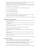
IMPORTANT SAFETY INFORMATION The information contained in this manual is intended for use by a qualified service technician who is familiar with the safety procedures required for installation and repair, and who is equipped with the proper tools and test instruments required to service this product.
• Do not spray or pour water on the return air grille, discharge air grille, evaporator coil, control panel, and sleeve on the room side of the air conditioning unit while cleaning. • Electrical component malfunction caused by water could result in electric shock or other electrically unsafe conditions when the power is restored and the unit is turned on, even after the exterior is dry. • Never operate the A/C unit with wet hands.
PROPERTY DAMAGE HAZARDS FIRE DAMAGE HAZARDS: • Read the Installation/Operation Manual for this air conditioning unit prior to operating. • Use air conditioner on a single dedicated circuit within the specified amperage rating. • Connect to a properly grounded outlet only. • Do not remove ground prong of plug. • Do not cut or modify the power supply cord. • Do not use extension cords with the unit. • Failure to follow these instructions can result in fire and minor to serious property damage.
Model Identification Guide MODEL NUMBER V E A 24 K 50 RT A SERIES V=Vertical Series ENGINEERING CODE E=Cooling with or without electric heat H=Heat Pump OPTIONS RT = Standard Remote Operation SP = Seacoast Protected DESIGN SERIES A = 32" and 47" Cabinet NOMINAL CAPACITY A-Series (Btu/h) 09 = 9,000 12 = 12,000 18 = 18,000 24 = 24,000 ELECTRIC HEATER SIZE A-Series 00 = No electric heat 25 = 2.5 KW 34 = 3.4 KW 50 = 5.0 KW 75 = 7.
2009 Chassis Specifications VEA/VHA09-24 VEA09K VEA12K VEA18K VEA24K VHA09K VHA12K VHA18K VHA24K C O O L I N G D A T A Cooling Btu/h 9500/9300 11800/11500 17500/17300 24000 9500/9300 11800/11500 17500/17300 23500 Cooling Power (W) 880 1093 1882 2526 905 1124 1882 2474 EER 10.8 10.8 9.3 9.5 10.5 10.5 9.3 9.5 Sensible Heat Ratio 0.74 0.72 0.70 0.70 0.74 0.72 0.70 0.70 H E A T P U M P D A T A Heating Btu/h N/A N/A N/A N/A 8500/8300 10600/10400 17000/16800 22500 COP @ 47°F N/A N/A N/A N/A 3.0 3.2 3.0 3.
2009 Extended Cooling Performance VEA - Extended Cooling Performance OUTDOOR DRY BULB TEMP. (DEGREES F AT 40% R.H.) 75 85 95 105 110 INDOOR WET BULB TEMP. (DEGREES F AT 80 F D.B.) 72 67 62 72 67 62 72 67 62 72 67 62 72 67 62 11172 10745 9947 10640 10032 9253 10222 9500 8408 9576 8503 7496 9049 7918 6987 WATTS 718 730 737 782 790 800 880 880 880 951 950 953 994 994 997 AMPS 3.4 3.4 3.5 3.7 3.7 3.7 4.1 4.10 4.1 4.4 4.4 4.4 4.6 4.6 4.6 SHR 0.
2008 Chassis Specifications VEA/VHA09-24 VEA09K C O O L I N G H E A P VEA12K VEA18K VEA24K VHA09K VHA12K VHA18K VHA24K D A T A Cooling Btu/h 9500/9300 11800/11500 18000/17800 24000 9500/9300 11800/11500 18000/17800 23500 Cooling Power (W) 880 1093 2070 2526 905 1124 2070 2474 EER 10.8 10.8 8.7 9.5 10.5 10.5 8.7 9.5 Sensible Heat Ratio 0.74 0.72 0.70 0.70 0.74 0.72 0.70 0.70 E A T P U M P D A T A Heating Btu/h N/A N/A N/A N/A 8500/8300 10600/10400 15700/15500 22500 COP @ 47°F N/A N/A N/A N/A 3.
2008 Extended Cooling Performance VEA - Extended Cooling Performance OUTDOOR DRY BULB TEMP. (DEGREES F AT 40% R.H.) 75 85 95 105 110 INDOOR WET BULB TEMP. (DEGREES F AT 80 F D.B.) BTUh VEA09 VEA12 VEA18 VEA24 WATTS 72 67 62 72 67 62 72 67 62 72 67 62 72 67 62 11172 10745 9947 10640 10032 9253 10222 9500 8408 9576 8503 7496 8522 7334 6479 718 730 737 782 790 800 880 880 880 951 950 953 1038 1038 1042 AMPS 3.4 3.4 3.5 3.7 3.7 3.7 4.1 4.10 4.1 4.
WARNING NOTICE ELECTRIC SHOCK HAZARD Turn off electric power before service or installation. All electrical connnections and wiring MUST be installed by a qualified electrician and conform to the National Electrical Code and all local codes which have jurisdiction. Failure to do so can result in personal injury and/or death. ELECTRIC SHOCK HAZARD Not following the previous WARNING could result in fire or electrically unsafe conditions which could cause moderate or serious property damage.
Remote Thermostat and Low Voltage Control Connections Cool Off Heat RT5 (Two speed fan) RT4 (One speed fan) Remote Thermostat Location All Friedrich Vert-I-Pak units are factory configured to be controlled by using a 24V single stage remote wall mounted thermostat. The thermostat may be auto or manual changeover as long as the control configuration matches that of the Vert-I-Pak unit.
Remote Thermostat and Low Voltage Control Connections (Continued) Thermostat Connections C = Common Ground W = Call for Heating Y = Call for Cooling R = 24V Power from Unit GL = Call for Fan (Low Speed) GH = Call for Fan (High Speed) B = Reversing Valve Energized in heating mode *If only one G terminal is present on thermostat, connect to GL for low fan or to GH for high fan operation.
ELECTRONIC CONTROL BOARD FEATURES The new Friedrich Vert-I-Pak has state of the art features to improve guest comfort and conserve energy. Through the use of specifically designed control software, Friedrich has accomplished what other Manufacturer’s have only attempted – a quiet, dependable, affordable and easy to use Vert-I-Pak. Below is a list of standard features on every Friedrich VPAK and their benefit to the owner.
Electronic Control Configuration The adjustable control dip switches are located at the lower left hand portion of the digital Smart Center. The inputs are only visible and accessible with the front cover removed from the Unit.
electronic control error codes diagnostics and test mode (Continued) The chart below lists the possible error codes and their description: Error Code Code Translation Action Taken by Unit Possible Cause EF “Error Free” - No Codes Stored None Unit Operating Normally 02 An extreme low voltage condition exists <198V for 230V units and <239V for 265V units. Shut down unit. Display Error code and flash. Once voltage rises to normal level system power is restored.
vpak electronic control board and wall thermostat sequence of operation Wall Thermostat Connections: • • • The control is compatible with a standard single stage heat and cool Wall Thermostat. It is compatible with Friedrich RT4 and RT5 Wall thermostats. Terminals are: C – Common ground terminal. W – call for heating. Y – call for cooling, R – 24V power from Electronic control to Wall Thermostat. GL - call for low Fan. GH- call for high fan B – call for heat pump reversing valve.
vpak electronic control board and wall thermostat sequence of operation (Continued) cool mode control features for cool with electric heat units Reversing valve: Always de-energized when “Cool” switch is selected on thermostat. Compressor operation: If ambient indoor temperature is above set point temperature depending on t-stat differential and the compressor is not time delayed, turn on compressor. If ambient indoor temperature is below set point depending on t-stat differential, turn off the compressor.
vpak electronic control board and wall thermostat sequence of operation (Continued) heat pump mode control features for heat pump with electric heat units Reversing valve: Always energized when “Heat” is selected on thermostat. Compressor operation depends on t-stat settings: If ambient indoor temperature is below the set point temperature depending on t-stat differential and the compressor is not time delayed, turn on compressor.
Component description / A-Series specifications VERT-I-PAK SINGLE PACKAGED VERTICAL AIR CONDITIONERS 9,000 / 12,000 / 18,000 / 24 K BTUs/h All units are factory assembled, piped, wired and fully charged with R-22. Units are ETL listed and carry an ETL label. Units are approved for 0” clearance. All units are factory run-tested to check operation. The 9,12 and 18 K BTUs units are 23 1/8” wide x 23 1/8” deep x 32 1/4” high. The 24 K BTUs unit is 23 1/8“ wide by 23 1/8” deep x 47 1/4“ high.
External Static Pressure External Static Pressure can best be defined as the pressure difference (drop) between the Positive Pressure (discharge) and the Negative Pressure (intake) sides of the blower. External Static Pressure is developed by the blower as a result of resistance to airflow (Friction) in the air distribution system EXTERNAL to the VERT-I-PAK cabinet. 7. Recheck the external static pressure with the new speed.
Determining the Indoor CFM: Chart A – CFM EXAMPLE: Measured voltage to unit (heaters) is 230 volts. Measured Current Draw of strip heaters is 11.0 amps. 230 x 11.0 = 2530 2530/1000 = 2.53 Kilowatts 2.53 x 3413 = 8635 Supply Air Return Air Temperature Rise 95°F 75°F 20 ° 20 x 1.08 = 21.6 8635 21.6 = 400 CFM ESP (") .00" .10" .20" .30” * ** VEA09/VHA09 Low High 340 385 300 340 230 280 140 190 The Vert-I-Pak units are designed for either single speed or two fan speed operation.
COMPONENTS TESTING BLOWER / FAN MOTOR A single phase permanent split capacitor motor is used to drive the evaporator blower and condenser fan. A self-resetting overload is located inside the motor to protect against high temperature and high amperage conditions. WARNING ELECTRIC SHOCK HAZARD Disconnect power to the unit before servicing. Failure to follow this warning could result in serious injury or death. BLOWER / FAN MOTOR TEST 1. Do a visual inspection of motor’s wiring, housing etc.
COMPONENTS TESTING (Continued) HEATER ELEMENTS AND LIMIT SWITCHES’ SPECIFICATIONS All heat pumps and electric heat models are equipped with a heating element and a limit switch (bimetal thermostat). The limit is in series with the element and will interrupt the power at a designed temperature. Should the blower motor fail, filter become clogged or airflow be restricted etc., the high limit switch will open and interrupt the power to the heater before reaching an unsafe temperature condition.
REFRIGERATION SEQUENCE OF OPERATION A good understanding of the basic operation of the refrigeration system is essential for the service technician. Without this understanding, accurate troubleshooting of refrigeration system problems will be more difficult and time consuming, if not (in some cases) entirely impossible. The refrigeration system uses four basic principles (laws) in its operation they are as follows: 1. “Heat always flows from a warmer body to a cooler body.” 2.
SERVICE WARNING ELECTRIC SHOCK HAZARD Turn off electric power before service or installation. Extreme care must be used, if it becomes necessary to work on equipment with power applied. Failure to do so could result in serious injury or death. WARNING CUT/SEVER HAZARD Be careful with the sharp edges and corners. Wear protective clothing and gloves, etc. Failure to do so could result in serious injury. Servicing / Chassis Quick Changeouts . To Remove the Chassis from the Closet: A.
SEALED REFRIGERATION SYSTEM REPAIRS IMPORTANT ANY SEALED SYSTEM REPAIRS TO COOL-ONLY MODELS REQUIRE THE INSTALLATION OF A LIQUID LINE DRIER. ALSO, ANY SEALED SYSTEM REPAIRS TO HEAT PUMP MODELS REQUIRE THE INSTALLATION OF A SUCTION LINE DRIER. EQUIPMENT REQUIRED: 1. Voltmeter 9. 2. Ammeter 10. Low Pressure Gauge - (30 - 150 lbs.) 3. Ohmmeter 11. Vacuum Gauge - (0 - 1000 microns) 4. E.P.A. Approved Refrigerant Recovery System EQUIPMENT MUST BE CAPABLE OF: 5.
Method Of Charging / Repairs The acceptable method for charging the RAC system is the Weighed in Charge Method. The weighed in charge method is applicable to all units. It is the preferred method to use, as it is the most accurate. The weighed in method should always be used whenever a charge is removed from a unit such as for a leak repair, compressor replacement, or when there is no refrigerant charge left in the unit. To charge by this method, requires the following steps: 1.
WARNING WARNING ELECTRIC SHOCK HAZARD Turn off electric power before service or installation. HIGH PRESSURE HAZARD Sealed Refrigeration System contains refrigerant and oil under high pressure. Extreme care must be used, if it becomes necessary to work on equipment with power applied. Proper safety procedures must be followed, and proper protective clothing must be worn when working with refrigerants. Failure to do so could result in serious injury or death.
Restricted Refrigerant System Troubleshooting a restricted refrigerant system can be difficult. The following procedures are the more common problems and solutions to these problems. There are two types of refrigerant restrictions: Partial restrictions and complete restrictions. A partial restriction allows some of the refrigerant to circulate through the system. With a complete restriction there is no circulation of refrigerant in the system.
HERMETIC COMPONENTS CHECK WARNING WARNING BURN HAZARD Proper safety procedures must be followed, and proper protective clothing must be worn when working with a torch. CUT/SEVER HAZARD Be careful with the sharp edges and corners. Wear protective clothing and gloves, etc. Failure to follow these procedures could result in moderate or serious injury. Failure to do so could result in serious injury. METERING DEVICE Capillary Tube Systems All units are equipped with capillary tube metering devices. 3.
REVERSING VALVE DESCRIPTION/OPERATION WARNING ELECTRIC SHOCK HAZARD Disconnect power to the unit before servicing. Failure to follow this warning could result in serious injury or death. The Reversing Valve controls the direction of refrigerant flow to the indoor and outdoor coils. It consists of a pressureoperated, main valve and a pilot valve actuated by a solenoid plunger. The solenoid is energized during the heating cycle only. The reversing valves used in the VPAK system is a 2-position, 4-way valve.
TESTING THE COIL WARNING ELECTRIC SHOCK HAZARD Unplug and/or disconnect all electrical power to the unit before performing inspections, maintenances or service. Failure to do so could result in electric shock, serious injury or death. The solenoid coil is an electromagnetic type coil mounted on the reversing valve and is energized during the operation of the compressor in the heating cycle. 1. Turn off high voltage electrical power to unit. 2. Unplug line voltage lead from reversing valve coil. 3.
Touch Test in Heating/Cooling Cycle WARNING BURN HAZARD Certain unit components operate at temperatures hot enough to cause burns. 6. Protect new valve body from heat while brazing with plastic heat sink (Thermo Trap) or wrap valve body with wet rag. 7. Fit all lines into new valve and braze lines into new valve. Proper safety procedures must be followed, and proper protective clothing must be worn. WARNING EXPLOSION HAZARD The use of nitrogen requires a pressure regulator.
COMPRESSOR CHECKS WARNING ELECTRIC SHOCK HAZARD Turn off electric power before service or installation. Extreme care must be used, if it becomes necessary to work on equipment with power applied. Failure to do so could result in serious injury or death. Checking the Overload WARNING Locked Rotor Voltage (L.R.V.) Test Locked rotor voltage (L.R.V.) is the actual voltage available at the compressor under a stalled condition. ELECTRIC SHOCK HAZARD Turn off electric power before service or installation.
Single Phase Resistance Test WARNING Many compressor failures are caused by the following conditions: 1. Improper air flow over the evaporator. 2. Overcharged refrigerant system causing liquid to be returned to the compressor. 3. Restricted refrigerant system. 4. Lack of lubrication. Remove the leads from the compressor terminals and set the ohmmeter on the lowest scale (R x 1). 5. Liquid refrigerant returning to compressor causing oil to be washed out of bearings.
COMPRESSOR REPLACEMENT Recommended procedure for compressor replacement WARNING RISK OF ELECTRIC SHOCK Unplug and/or disconnect all electrical power to the unit before performing inspections, maintenances or service. Failure to do so could result in electric shock, serious injury or death. 1. Be certain to perform all necessary electrical and refrigeration tests to be sure the compressor is actually defective before replacing. WARNING 3.
SPECIAL PROCEDURE IN THE CASE OF MOTOR COMPRESSOR BURNOUT WARNING ELECTRIC SHOCK HAZARD Turn off electric power before service or installation. Failure to do so may result in personal injury, or death. WARNING HIGH PRESSURE HAZARD Sealed Refrigeration System contains refrigerant and oil under high pressure. Proper safety procedures must be followed, and proper protective clothing must be worn when working with refrigerants. Failure to follow these procedures could result in serious injury or death.
ROUTINE MAINTENANCE WARNING ELECTRIC SHOCK HAZARD Turn off electric power before inspections, maintenances, or service. Extreme care must be used, if it becomes necessary to work on equipment with power applied. NOTICE Units are to be inspected and serviced by qualified service personnel only. Use proper protection on surrounding property. Failure to follow this notice could result in moderate or serious property damage. Failure to do so could result in serious injury or death.
ROUTINE MAINTENANCE (Continued) NOTICE Do not drill holes in the bottom of the drain pan or the underside of the unit. Not following this notice could result in damage to the unit or condensate water leaking inappropriately which could cause water damage to surrounding property. SLEEVE / DRAIN Inspect the sleeve and drain system periodically (at least yearly or bi-yearly) and clean of all obstructions and debris. Clean both areas with an antibacterial and antifungal cleaner.
ELECTRICAL TROUBLESHOOTING CHART - COOLING 9K BTU, 12K BTU, & 18K BTU NO COOLING OPERATION Before continuing check for Error Codes, see electronics control diagnostics and test mode, page 15 Insure that Fuses are good and/or that Circuit Breakers are on and voltage is 208/230 O.K. Set thermostat to "Cool," and the Temp. below the present Room Temp. O.K.
ELECTRICAL TROUBLESHOOTING CHART - COOLING 24K BTU NO COOLING OPERATION Before continuing check for Error Codes, see electronics control diagnostics and test mode, page 15 Insure that Fuses are good and/or that Circuit Breakers are on and voltage is 208/230 O.K. Set thermostat to "Cool," move the Temp. lever below the present Room Temp. O.K.
ELECTRICAL TROUBLESHOOTING CHART HEAT PUMP HEAT PUMP MODE SYSTEM COOLS WHEN HEATING IS DESIRED.
TROUBLESHOOTING CHART - COOLING REFRIGERANT SYSTEM DIAGNOSIS COOLING PROBLEM LOW SUCTION PRESSURE PROBLEM PROBLEM PROBLEM HIGH SUCTION PRESSURE LOW HEAD PRESSURE HIGH HEAD PRESSURE High Load Conditions Low Load Conditions High Load Conditions Low Load Conditions Low Air Flow Across Indoor Coil High Air Flow Across Indoor Coil Refrigerant System Restriction Refrigerant System Restriction Reversing Valve not Fully Seated Undercharged Overcharged Moisture in System Defective Compressor Low
COOL WITH ELECTRIC HEAT ELECTRICAL & THERMOSTAT WIRING DIAGRAM VEA 09/12/18 with 2.5 KW, 3.4 KW or 5KW ELECTRIC HEAT NOTE: 44 THE DIAGRAM ABOVE, ILLUSTRATES THE TYPICAL THERMOSTAT WIRING FOR TWO SPEED FAN OPERATION. SEE THE UNIT CONTROL PANEL FOR THE ACTUAL UNIT WIRING DIAGRAM AND SCHEMATIC.
HEAT PUMP WITH ELECTRIC HEAT ELECTRICAL & THERMOSTAT WIRING DIAGRAM VHA 09/12/18 with 2.5 KW, 3.4 KW or 5KW ELECTRIC HEAT NOTE: THE DIAGRAM ABOVE, ILLUSTRATES THE TYPICAL THERMOSTAT WIRING FOR TWO SPEED FAN OPERATION. SEE THE UNIT CONTROL PANEL FOR THE ACTUAL UNIT WIRING DIAGRAM AND SCHEMATIC.
COOL WITH ELECTRIC HEAT ELECTRICAL & THERMOSTAT WIRING DIAGRAM VEA 24 with 2.5 KW, 3.
HEAT PUMP WITH ELECTRIC HEAT ELECTRICAL & THERMOSTAT WIRING DIAGRAM VHA 24 with 2.5 KW, 3.
COOL WITH ELECTRIC HEAT ELECTRICAL & THERMOSTAT WIRING DIAGRAM VEA 24 with 7.
HEAT PUMP WITH ELECTRIC HEAT ELECTRICAL & THERMOSTAT WIRING DIAGRAM VHA 24 with 7.
RESISTANCE VALUES FOR THERMISTORS ON ELECTRONIC CONTROL BOARD Outdoor Coil Return Air 50 Indoor Coil
ACCESSORIES MODE L DE SCRIP T ION PHO T O WALL PLENUM VPAWP1-8 1 2 3 1 8 7 8 5 8 8 VPAWP1-14 ARCHITECTURAL LOUVER VPAL2 1 16 9 16 VPSC2 RT4 DIGITAL REMOTE WALL THERMOSTAT Single stage thermostat, used on VERT-I-PAK units. Hard wired with single speed fan. Direct replacement for RT2. RT5 DIGITAL REMOTE WALL THERMOSTAT Single stage thermostat. Features high/low fan speed switch. Thermostat is hard wired and can be battery powered or unit powered.
Friedrich Air Conditioning Company P.O. Box 1540 San Antonio, TX 78295 210.357.4400 www.friedrich.com VERT-I-PAK® A SERIES SINGLE PACKAGE VERTICAL AIR CONDITIONERS LIMITED WARRANTY SAVE THIS CERTIFICATE. It gives you specific rights. You may also have other rights which may vary from state to state and province to province. In the event that your unit needs servicing, contact your nearest authorized service center.
TECHNICAL SUPPORT CONTACT INFORMATION FRIEDRICH AIR CONDITIONING CO. Post Office Box 1540 · San Antonio, Texas 78295-1540 4200 N. Pan Am Expressway · San Antonio, Texas 78218-5212 (210) 357-4400 · FAX (210) 357-4490 www.friedrich.com Printed in the U.S.A.
FRIEDRICH AIR CONDITIONING CO. Post Office Box 1540 · San Antonio, Texas 78295-1540 4200 N. Pan Am Expressway · San Antonio, Texas 78218-5212 (210) 357-4400 · FAX (210) 357-4490 www.friedrich.com Printed in the U.S.A.