Service Manual 2003 Room Air Conditioners RACServMn (7-03)
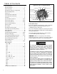
Table of Contents Unit Identification ............................................... 3 Unit Specifications ............................................. 4 Unit Performance ......................................... 5-11 Refrigeration Sequence of Operation .............. 12 Electrical Rating Tables ................................... 13 Compressor ..................................................... 14 Thermal Overload (External) ........................... 14 Thermal Overload (Internal) ...................
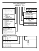
UNIT IDENTIFICA TION IDENTIFICATION Model Number Code S S 08 J 1 0 R 1st Digit – Function S = Straight Cool, Value Series C = Straight Cool, Budget Series Y = Heat Pump E = Electric Heat K = Straight Cool, Challenger Series W = Thru-the Wall, WallMaster Series 8th Digit – Engineering Major change 7th Digit – Options 0 = Straight Cool & Heat Pump Models 1 = 1 KW Heat Strip, Normal 3 = 3 KW Heat Strip, Normal 4 = 4 KW Heat Strip, Normal 5 = 5 KW Heat Strip, Normal 8 = 8 KW Heat Strip, Normal 6th Digit – V
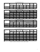
PERFORMANCE DATA* Cooling EQ08J11-A EQ08J11-B DATA* Cooling XQ05J10B XQ06J10-A XQ06J10-B XQ07J10-1 XQ08J10-1 XQ08J10-A PERFORMANCE DATA* Cooling SQ05J10B-B SQ06J10B-A SQ06J10B-B SQ08J10C-1 PERFORMANCE DATA* Cooling KQ05J10B-B KQ05E10-B KQ05E10-C KQ06J10B-A KQ06J10B-B KQ06E10-A KQ06E10-B YQ06J10B-A EQ PERFORMANCE DATA EVAPORATOR AIR OPERATING ELECTRICAL TEMP. DEG. F. PRESSURES RATINGS Discharge Temp. Suction Discharge Amps Locked Air Drop F. Rotar Amp 50.5 29.5 72 262 7.5 39.2 50.5 29.5 74 259 7.5 39.
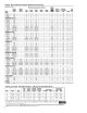
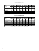
RS-RM PERFORMANCE DATA PERFORMANCE DATA* Cooling RS10J10-C RS12J10A-B RS15J10-A RS16J30A-A RS18J30-A RM24J30-A EVAPORATOR AIR TEMP. DEG. F. Discharge Temp. Air Drop F. 61 19 57 23 57 23 56.5 24 56 24 57 23.65 OPERATING PRESSURES Suction Discharge 82 83 77 77 72 68 248 271 279 296 293 301 R-22 BREAKER ELECTRICAL REFRIG. FUSE RATINGS Amps Locked Charge in 60 Hertz Rotar Amp OZ. Amps 7.5 44 26 15 9.8 54 30 15 11.1 42 29.5 15 7.2 42 30 15 8.7 42 48 15 12.
PERFORMANCE DATA* Cooling ES12J33B-A ES16J33A-A EM18J34B-A EL25J35-A EL35J35-A EL35J35-B PERFORMANCE DATA heating ES12J33B-A ES16J33A-A EM18J34B-A EL25J35-A EL35J35-A EL35J35-B EVAPORATOR AIR TEMP. DEG. F. Discharge Temp. Air Drop F. 58 22 53 27 55 25 55 25 52 28 52 28 OPERATING PRESSURES Suction Discharge 82 77 71 75 72 72 265 269 267 284 317 317 ELECTRICAL R-22 BREAKER RATINGS REFRIG. FUSE Amps Locked Charge in 60 Hertz Rotar Amp OZ. Amps 5.76.6 26.3 28 20 7.5/8.0 42.'0 30 20 8.6/9.2 42.'0 40.5 30 11.
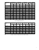
SS PERFORMANCE DATA PERFORMANCE DATA* Cooling SS08J10R-B SS08J10R-A SS09J10C-A SS10J10AR-A SS12J10AR-B SS14J10R-A SS12J30D-A SS16J30A-A SS18J30R-A EVAPORATOR AIR TEMP. DEG. F. Discharge Temp. Air Drop F. 61.4 18.6 61.4 18.6 57.8 22.2 57.22 22.78 57.2 22.8 57.22 22.9 57.2 22.8 56.9 23 56.9 23 OPERATING PRESSURES Suction Discharge 87 84 82 84 83 77 82 77 77 251 248 254 245 271 279 265 296 293 ELECTRICAL R-22 BREAKER RATINGS REFRIG. FUSE Amps Locked Charge in 60 Hertz Rotar Amp OZ. Amps 6.7 29 39.'0 15 6.
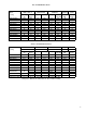
WS PERFORMANCE DATA PERFORMANCE DATA* Cooling WS07A10E-B WS07A10E-C WS07A10E-D WS10A10-A WS10A10-B WS12A10E-B WS13A10-A WS09A30E-B WS12A30E-A WS12A30E-B WS15A30-A EVAPORATOR AIR TEMP. DEG. F. Discharge Temp. Air Drop F. 59.5 19.5 59.5 19.5 59.5 19.5 58 22 58 22 55 25 55 25 58 22 47.1 32.9 46 33 47 33 OPERATING PRESSURES Suction Discharge 84 85 85 83 83 81 79 86 80 80 72 300 299 299 307 307 290 281 302 308 305 310 ELECTRICAL R-22 BREAKER RATINGS REFRIG. FUSE Amps Locked Charge in 60 Hertz Rotar Amp OZ.
SPECIFICATIONS PERFORMANCE DATA* SC06H10E SC06H10E DISCHARGE 56.1 BTUH (Cooling) 5950 E.E.R. (Cooling) 8.0 EVAPORATOR AIR AIR Volts 115 TEMP. °F TEMP Amperes (Cooling) 6.8 Total Watts (Cooling) 760 OPERATING SUCTION 72 Hertz 60 PRESSURES DISCHARGE 293 Fuse/Breaker Size 15 AMPS 6.8 LOCKED 35.0 DROP °F Fan RPM 1595 ELECTRICAL Evaporator Air CFM 125 RATINGS Dehumidification Pts/Hr 2.0 ROTOR AMPS Width 1411/16" R-22 CHARGE IN Height 1013/16" REFRIG.
PERFORMANCE DATA (Heating) BTUH ** *WY09A33F-A *WY12A33F-A 9700 9300 8800 8200/8100 7600 6800 11000/9100 12400 12000 11400 10800/10400 10000 9000 11000/9100 @70°F Inside 62°F Outside @70°F Inside 57°F Outside @70°F Inside 52°F Outside @70°F Inside 47°F Outside @70°F Inside 42°F Outside @70°F Inside 37°F Outside @70°F Inside 35°F Outside 32.00 30.75 29.10 27.10/26.80 25.10 22.50 36.40/30.10 37.60 36.40 34.50 32.70/31.50 30.30 27.30 33.30/27.60 @70°F Inside 62°F Outside 4.0 5.
Refrigeration System Sequence of Operation A good understanding of the basic operation of the refrigeration system is essential for the service technician. Without this understanding, accurate troubleshooting of refrigeration system problems will be more difficult and time consuming, if not (in some cases) entirely impossible. The refrigeration system uses four basic principles (laws) in its operation they are as follows: 1. "Heat always flows from a warmer body to a cooler body." 2.
Electrical Rating T ables Tables Circuit Rating Breaker or T-D Fuse Plug Face (NEMA#) 125V - 15A 5 - 15P KS12J30B, KM18J30C, RS16J30A, RM18J30A, SS12J30D, SS16J30A, SM18J30BR 250V - 15A 6 - 15P KM20J30, KM24J30, SM20J30, SL25J30, SL28J30B*, ES12J33B, ES16J33A, YS12J33 250V - 20A 6 - 20P SL35J30, EM18J34B, EL25J35, EL35J35, YM18J34B, YL24J35C 250V - 30A 6 - 30P Model ALL SV and XQ MODELS, KS10J10, KS12J10B, KS15J10, RS10J10, RS12J10A, RS15J10, SS08J10R, SS09J10C, SS10J10AR, SS12J10AR, SS14J10R,
COMPONENTS: OPERATION & TESTING Figure 2 Typical Ground Test WARNING DISCONNECT ELECTRICAL POWER TO UNIT BEFORE SERVICING OR TESTING COMPRESSORS Compressors are single phase, 115 or 230/208 volt, depending on the model unit. All compressor motors are permanent split capacitor type using only a running capacitor across the start and run terminal. All compressors are internally spring mounted and externally mounted on rubber isolators.
Heat generated within the compressor shell is usually due to: FAN MOTOR - TEST 1. Determine that capacitor is serviceable. 1. High amperage 2. Low refrigerant charge 2. Disconnect fan motor wires from fan speed switch or system switch. 3. Apply "live" test cord probes on black wire and common terminal of capacitor. Motor should run at high speed. 4. Apply "live" test cord probes on red wire and common terminal of capacitor. Motor should run at low speed. 5.
SYSTEM CONTROL SWITCH - TEST (See Figure 7) Disconnect the leads from the control switch. There must be continuity as follows: Rocker Switch Figure 8 1. "Off" Position - no continuity between terminals. 2. "Lo Cool" Position - between terminals "L1" and "C", "Lo" and MS". 3. "Med Cool" Position - between terminals "L1" and "C", "M" and "MS". 4. "Hi Cool" Position - between terminals L1" and "C", "H" and "MS". 5. "Fan Only" Position - between terminals "L1" and "2".
SYSTEM CONTROL PANEL ("KQ" Models Only- See Figure 10) The KQ Model unit uses a five position control switch to regulate the operation of the unit. Function of each position (clockwise rotation) is as follows: SYSTEM CONTROL PANEL EQ Model Only (See Figure 12 ) The EQ Model unit uses a six-position control switch to regulate the operation of the unit. Function of each position (clockwise rotation) is as follows: 1. “Off” Turns everything off. Figure 10 System Control Panel (KQ Models Only) 2.
Figure 13 System Control Switch (EQ Models) 4. "Lo Heat" Position - between terminals "C" and "2", and "C" and "4". L1 B1 L2 MS H C LO 2 5. "Hi Heat" Position - between terminals "C" and "1", and "C" and "4". ROTARY (SYSTEM) SWITCH: "SC" Model (See Figure 16) A rotary four position switch is used to turn on the unit and select the operation desired.
Figure 16 System Control Switch (SC Model Only) 1. Disconnect leads from control switch. 2. Check continuity between all switch positions shown in Figure 17. SYSTEM CONTROL PANEL "WS" Models (See Figure 18) A five position control switch is used to regulate the operation of the fan motor and compressor. The compressor can be operated with the fan operating at low, medium or high speed. The fan motor can also be operated independently on medium speed.
6. "Med Heat" Position-between terminals "C" and "1", "C2" and "4", "M" and "M/S", "AR" and "5". 7. "Lo Cool" Position-between terminals "C" and "1", "C2" and "4", "LO" and "M/S", "AR" and "5". 8. "Fan Only" Position-between terminals "L1" and "M". SYSTEM CONTROL SWITCH - TEST (See Figure 23) Disconnect leads from control switch. There must be continuity as follows: 1. "Off" Position - no continuity between terminals. 2. "Lo Cool" Position - between terminals "L1" and "C," "LO" and "MS." 3.
SYSTEM CONTROL SWITCH - TEST Disconnect leads from control switch (See Figure 25) There must be continuity as follows: Figure 25 SYSTEM CONTROL SWITCH (Heat Pump & Electric Heat Models) (See Figure 27) An eight position control switch is used to regulate the operation of the fan motor and compressor. The compressor can be operated with the fan operating at low, medium or high speed in the cooling or heating mode. The fan motor can also be operated independently on medium speed.
SYSTEM CONTROL SWITCH - TEST (See Figure 28) Disconnect leads from control switch. Turn control to position being tested. There must be continuity as follows: TO ADJUST TEMPERATURE COOLER - Touch COOLER to see setting, touch again to change. 1. "Off" Position - no continuity between terminals. WARMER - Touch WARMER to see setting, touch again to change. 2. "Lo Cool" Position - between terminals "C" and "3", "C2" and "2", "LO" and "M/S", "AR" and "5". 3.
TO SET HOUR CLOCK Touch SET HOUR CLOCK to see setting. To change, touch and hold until hour closest to the actual time appears in the display. MAKE SURE A.M. AND P.M. ARE SET PROPERLY. (Minutes will NOT show on display.) TO SET THE TIMER NOTE: SET HOUR CLOCK before attempting to set timer functions. The TIMER ON/OFF times can be set a minimum of one hour apart and a maximum of twenty-three hours apart. STOP TIME - Touch A/C STOP and hold until the hour the unit needs to shut off appears in the display A.M.
(QME Units) The Fan Speed button and the Warmer button. ( XQ Units) The Fan Speed button and the Temp Up button. The indoor temperature will be displayed for 10 seconds. The display will change back to the Set Point temperature by pressing any key button except for the On/Off button. The indoor temperature can be viewed in all modes, including test mode. Filter Alert: The Filter Alert indicator turns on after the fan motor has been operating for 250 hours.
In the heating cycle, the heat anticipator is energized to supply a small amount of heat during the "on" cycle. This will open the contacts in the thermostat prematurely to maintain a closer differential between the "cut in" and "cut out" temperature. The heat anticipator is energized in the heating mode regardless of whether fan is placed in the automatic (MoneySaver) or constant run position.
DEFROST BULB LOCATION (Heat Pump Models Only) (See Figure 36) The defrost control bulb must be mounted securely and in the correct location to operate properly. CAPACITOR, RUN (See Figure 38) A run capacitor is wired across the auxiliary and main winding of a single phase permanent split capacitor motor such as the compressor and fan motor. A single capacitor can be used for each motor or a dual rated capacitor can be used for both.
CHECK VALVE (See Figure 39) A unique two-way check valve is used on the reverse cycle heat pumps. It is pressure operated and used to direct the flow of refrigerant through a single filter drier and to the proper capillary tube during either the heating or cooling cycle Figure 40 Figure 39 One-way Check Valve (Heat Pump Models) (TO INDOOR COIL) NOTE: The slide (check) inside the valve is made of teflon.
There are three tubes connected to one side of the main valve body and one tube on the opposite side. The single tube is connected to the compressor discharge line. The center tube on the opposite side is the common suction line to the compressor. The outside tubes are connected to the indoor and outdoor coils. The pivot valve is responsible for directing the refrigerant flow to the indoor or outdoor coil. There are three small tubes connected to the pilot valve body.
VALVE, DRAIN PAN (See Figure 43) During the cooling mode of operation, condensate which collects in the drain pan is picked up by the condenser fan blade and sprayed onto the condenser coil. This assists in cooling the refrigerant plus evaporating the water. During the heating mode of operation, it is necessary that water be removed to prevent it from freezing during cold outside temperatures. This could cause the condenser fan blade to freeze in the accumulated water and prevent it from turning.
microns. Pressure system to 5 PSIG and leave in system a minimum of 10 minutes. Release refrigerant, and proceed with evacuation of a pressure of 200 microns or less. EQUIPMENT MUST BE CAPABLE OF: 1. Recovery CFC's as low as 5%. 2. Evacuation from both the high side and low side of the system simultaneously. 11. 3. Introducing refrigerant charge into high side of the system. 4. Accurately weighing the refrigerant charge actually introduced into the system.
Proper refrigerant charge is essential to proper unit operation. Operating a unit with an improper refrigerant charge will result in reduced performance (capacity) and/or efficiency. Accordingly, the use of proper charging methods during servicing will insure that the unit is functioning as designed and that its compressor will not be damaged. Too much refrigerant (overcharge) in the system is just as bad (if not worse) than not enough refrigerant (undercharge).
NOTE: Heat pump refrigeration drawing Overcharged Refrigerant Systems Compressor amps will be near normal or higher. Noncondensables can also cause these symptoms. To confirm, remove some of the charge, if conditions improve, system may be overcharged. If conditions don’t improve, Noncondensables are indicated. Whenever an overcharged system is indicated, always make sure that the problem is not caused by air flow problems.
Restricted Refrigerant System A quick check for either condition begins at the evaporator. With a partial restriction, there may be gurgling sounds at the metering device entrance to the evaporator. The evaporator in a partial restriction could be partially frosted or have an ice ball close to the entrance of the metering device. Frost may continue on the suction line back to the compressor.
Routine Maintenance NOTE: Units are to be inspected and serviced by qualified service personnel only. 1. Clean the unit air intake filter at least every 250 to 300 fan hours of operation or when the unit's indicator light is on if so equipped. Clean the filters with a mild detergent in warm water and allow to dry thoroughly before reinstalling. 2.
Troubleshooting Touch Test Chart: To Service Reversing Valves Cool Hot Cool 4 RIGHT Pilot Capillary Tube 3 LEFT Pilot Capillary Tube Tube to OUTSIDE COIL 2 Hot Tube to INSIDE COIL 1 Normal Cooling Normal Heating SUCTION TUBE to Compressor VALVE OPERATING CONDITION DISCHARGE TUBE from Compressor NORMAL FUNCTION OF VALVE 5 6 Cool Hot *TVB as (2) as (1) Hot Cool *TVB as (1) as (2) NOTES: * TEMPERATURE OF VALVE BODY ** WARMER THAN VALVE BODY POSSIBLE CAUSES CORRECTIONS TVB TVB MALFUNCTION
Troubleshooting: Cooling POSSIBLE CAUSE PROBLEM Low voltage. Compressor does not run. Thermostat not set cold enough or inoperative. Compressor hums but cuts off on overload. Open or shorted compressor windings. Open overload. Open capacitor. Inoperative system switch. Broken, loose or incorrect wiring. PROBLEM POSSIBLE CAUSE Inoperative system switch. Broken, loose or incorrect wiring. Open Capacitor. Fan speed switch open. Inoperative fan motor. Fan motor does not run.
PROBLEM Evaporator coil freezes up. PROBLEM POSSIBLE CAUSE Dirty filter. Restricted air flow. Inoperative thermostat. Short of refrigerant. Inoperative fan motor. Partially restricted capillary. POSSIBLE CAUSE Thermostat incorrectly wired. TO CORRECT: Unit undersized. Test cooling performance of unit. Replace with larger unit. Check for partially iced coil. Check temperature split across coil. Check for oil at silver soldered connections. Check for partially iced coil. Check split across coil.
PROBLEM POSSIBLE CAUSE TO CORRECT Poorly installed unit. Improperly mounted or loose cabinet parts. Refer to Installation Instructions for proper installation. Reposition - adjust motor mount. Check that compressor grommets have not deteriorated. Check that compressor mounting parts are not missing, and that shipping blocks have been removed. Check assembly and parts for looseness, rubbing and rattling. POSSIBLE CAUSE TO CORRECT Evaporator drain pan overflowing. Condensation forming on base pan.
PROBLEM Outside water leaks. POSSIBLE CAUSE TO CORRECT Evaporator drain pan cracked or obstructed. Water in compressor area. Repair, clean or replace as required. Obstructed condenser coil. Fan blade and slinger ring improperly positioned. PROBLEM High indoor humidity. Detach shroud from pan and coil. Clean and remove old sealer. Reseal, reinstall and check. Steam clean. Adjust fan blade to 1/2" clearance from condenser coil.
Troubleshooting: Heating (Heat pumps) PROBLEM POSSIBLE CAUSE TO CORRECT Thermostat setting. Defective thermostat. Compressor not operating. Defective system switch. Set thermostat to a warmer position. Replace — do not attempt to adjust. Check compressor wiring. Check for open internal or external overload. Check wiring. Test system switch PROBLEM POSSIBLE CAUSE TO CORRECT Insufficient heating. Restricted filter. Outdoor thermostat. (Applicable models.) Clean as recommended in Owner’s Manual.
PROBLEM Unit does not heat adequately. PROBLEM Unit cools when heat is called for. POSSIBLE CAUSE Outdoor thermostat does not cut off Defective thermostat - replace. compressor at the preselected temperature and bring on heating element. Fresh air or exhaust door open. Check if operating properly. Instruct customer on proper use of control. Dirty filter. Clean as recommended in Owner’s Manual. Unit undersized. Check heat rise across coil.
PROBLEM Compressor will not turn off and operate on heating element only during low outside ambients. PROBLEM POSSIBLE CAUSE TO CORRECT Outdoor thermostat. (Applicable models.) Refer to the heating data on applicable models for the preselected temperature the compressor shuts off and the electric element is energized. POSSIBLE CAUSE Fuse link. TO CORRECT Check fuse link for continuity. If defective, replace. Compressor shuts off on Heating element shorted.
Troubleshooting: Heating (Cooling/Electric Models) PROBLEM Fan Operates – heating element does not come on. POSSIBLE CAUSE Heater relay or contactor coil open. Heater relay or contactor stuck open, pitted or burned. High limit control open. Open thermal fuse. Open or shorted element. Loose connections. PROBLEM POSSIBLE CAUSE Restricted filter. Cycling high limit control. Heating inadequate. PROBLEM POSSIBLE CAUSE Fan relay contacts open.
PROBLEM POSSIBLE CAUSE TO CORRECT Compressor will not turn off and operate on heating element only during low outside ambients. Outdoor thermostat. (Applicable models.) Refer to the heating data on applicable models for the preselected temperature the compressor shuts off and the electric element is energized.
Troubleshooting Chart — Heating REFRIGERANT SYSTEM DIAGNOSIS – HEATING Low Suction Pressure High Suction Pressure High Head Pressure Low Head Pressure Low Airflow Across Outdoor Coil Outdoor Ambient Too High for Operation in Heating Refrigerant System Restriction Refrigerant System Restriction Reversing Valve not Fully Seated Reversing Valve not Fully Seated Low Airflow Across Indoor Coil Undercharged Overcharged Undercharged Overcharged Moisture in System Defective Compressor Defective Com
MODELS RS10J10C, RS12J10A-B, RS15J10A, RS16J30A-A, RS18J30A, RM24J30-A COMPRESSOR TERMINAL ORIENTATION MAY VARY.
MODELS SQ06J10B-B, SQ06J10B-A, SQ08J10C-A, SQ08J10D-A WIRING DIAGRAM RED PURPLE COMPRESSOR BLUE C L1 MS R S BLUE "F" H C 2 "F" "F" M L SWITCH SYSTEM 2 THERMOSTAT 2 GREY WHITE RED ANTICIPATOR RESISTOR OPTIONAL CONFIGURATION SUPPLY CORD 1 BLACK SWITCH ROCKER (GE) BLACK 1 3 BLUE HARNESS, COMPR.
MODELS KQ05J10B-B, KQ05E10-C KQ06J10B-A, KQ06J10B-B, KQ06E10-A, KQ06E10-B WIRING DIAGRAM PTCR (OPTIONAL) CAPACITOR RED FAN MOTOR BLACK C FAN WHITE WIRE HARNESS BROWN BLACK RED HERM BLACK BLUE R S RIBBED (OR BLUE) CONDUCTOR RED C COMPRESSOR BLACK THERMOSTAT BLACK 2 L H C BLACK 1 SYSTEM SWITCH L1 GREEN/YELLOW SMOOTH (OR BROWN) CONDUCTOR SEE DETAIL " A " TO GND SCREW SUPPLY CORD DETAIL " A " OPTIONAL WIRING RED BLACK SYSTEM SWITCH SEQUENCE BLK 2 CW ROT CONNECTION OFF AL
MODELS KQ08J10B-1, KQ08J10B-A, KQ08J10C-A WIRING DIAGRAM WIRE HARNESS R S C CAPACITOR PTCR (OPTIONAL) RED BLACK R S C FAN 04 1 FAN MOTOR WHITE C BROWN BLUE NOTE: BLACK OPTIONAL CONFIGURATION RED HERM BLACK BLUE RED BLACK BLUE THERMOSTAT 2 BLK L 1 H C BLACK L1 GREEN SYSTEM SWITCH BROWN BROWN SEE DETAIL " A " TO GND SCREW SUPPLY CORD DETAIL " A " OPTIONAL WIRING RED 04 BLACK SYSTEM SWITCH SEQUENCE 2 CW ROT CONNECTION OFF ALL OPEN HI FAN LO FAN LO COOL HI COOL L1-H L1
MODELS XQ05J10-B, XQ06J10-A, XQ06J10-B, XQ08J10-1, XQ08J10-A, XQ08J10A-A SMOOTH CONDUCTOR OR BROWN RELAY BLACK RELAY BLUE COM NO RELAY RED RIBBED CONDUCTOR BLACK WHITE WHITE CAPACITOR c RED BLUE BLACK BROWN RED SUPPLY CORD HIGH MEDIUM LOW BLACK COMPRESSOR WIRE HARNESS GREEN OR GREEN/YELLOW OVERLOAD PROTECTOR BLACK WIRING DIAGRAM TRANSFORMER WHITE C RED S BLUE R ELECTRONIC CONTROL TO CAPACITOR BRACKET HER M FAN OR BLUE COMPRESSOR TERMINAL ORIENTATION MAY VARY.
MODEL YQ06J10B-A BLACK RED WIRING DIAGRAM PTCR (OPTIONAL) BLUE RED BLACK BLUE BLACK CAPACITOR RED RED RIBBED (OR BLUE) CONDUCTOR WHITE FAN C (HARNESS, COMPR.
MODEL: SC06H10D 52
MODELS SS08J10R-B, SS08J10R-A, SS09J10C-A, SS10J10AR-A, SS12J10AR-B, SS14J10R-A, SS12J30D-A, SS16J30A-A, SS18J30R-A, SM20J30-A, SM24J30-A WHITE TRANSFORMER RED BLACK ALTERNATE COMPRESSOR NO COM BLACK RELAY BLUE COMPRESSOR WIRE HARNESS BLACK RELAY ORANGE ROOM SENSOR RED RELAY RIBBED CONDUCTOR DEFROST SENSOR ELECTRONIC CONTROL CAPACITOR WHITE WHITE BROWN c SUPPLY CORD RELAY RED ORANGE BLUE BLACK RED GREEN OR GREEN/YELLOW BLACK OVERLOAD PROTECTOR R SMOOTH CONDUCTOR OR BROWN BLUE R
MODELS SL28J30B-A, SL35J30-A, SL35J30-B COMPRESSOR BLUE R R RED RED PURPLE BLACK SYSTEM SWITCH ALTERNATE COMPRESSOR C BLUE MS OVERLOAD PROTECTOR L1 "F" "F" BLUE H S 2 C "F" WIRING DIAGRAM COMPRESSOR TERMINAL ORIENTATION MAY VARY. REFER TO MARKING ON COMPRESSOR.
MODELS KS10E10-A, KS10J10-B, KS12E10-A, KS12J10B-A, KS15J10-A, KS12J30B-A, KS18J30-A, KM20J30-A, KM24J30-A COMPRESSOR BLUE R R RED RED PURPLE BLACK SYSTEM SWITCH ALTERNATE COMPRESSOR C BLUE MS OVERLOAD PROTECTOR L1 "F" "F" BLUE H S 2 C "F" WIRING DIAGRAM COMPRESSOR TERMINAL ORIENTATION MAY VARY. REFER TO MARKING ON COMPRESSOR.
MODELS ES12J33B-A, ES16J33A-A, EM18J34B-A, EL25J35-A, EL35J35-B, EK18J34A WIRING DIAGRAM RED BLUE COMPRESSOR TERMINAL ORIENTATION MAY VARY.
MODELS YS12J33-A, YM18J34B-A, YL24J35C-A RED BLUE SYSTEM SWITCH MS COMPRESSOR 4 2 L1 BLUE BROWN H M L C2 WHITE C AR RED BLACK GRAY BLACK PINK BLACK BLACK ORANGE PURPLE BLUE WHITE YELLOW OVERLOAD PROTECTOR WHITE BLACK BLUE ORANGE BROWN BLACK FAN MOTOR PURPLE c FAN TO CAPACITOR BRACKET TO CAPACITOR BRACKET RED HE RM GREEN OR GREEN/ YELLOW GREEN ORANGE RED RED BLUE RIBBED CONDUCTOR OR BLUE GREEN OR GREEN/YELLOW TO INNERWALL/ MOTOR MOUNT ROCKER SWITCH (GE) 3 2 ANTICIPATOR RESI
MODEL YS09J10B-A RED BLUE MS ALTERNATE BROWN COMPRESSOR C AR 2 L1 M H L C2 SMOOTH CONDUCTOR OR BROWN RED BLUE RED GRAY BLACK PINK WHITE ORANGE PURPLE BLUE WHITE BLACK OVERLOAD PROTECTOR WHITE BLACK BLUE ORANGE BROWN 3 1 2 PINK FAN MOTOR PURPLE RED c RIBBED CONDUCTOR OR BLUE RED BLUE FAN HE RM GREEN GREEN OR GREEN/ YELLOW 3 2 ROCKER SWITCH (GE) ANTICIPATOR RESISTOR 1 BLUE BLACK OR WHITE GREEN OR GREEN/YELLOW TO INNERWALL/ MOTOR MOUNT SUPPLY CORD YELLOW R BLUE C GRA
MODELS EQ08J11-A, EQ08J11-B BLUE WIRING DIAGRAM CONDUCTOR YELLOW COMPRESSOR L1 * 2 MS C S R BLUE * "F" L2 C * RED "F" "F" H L * HARNESS, COMPR.
MODELS WS07A10E-B, WS07A10E-C, WS10A10-A, WS12A10E-A, WS09A30E-B, WS12A30E-A, WS15A30-A WIRING DIAGRAM COMPRESSOR BLUE R C S H L1 BLACK MS RED C PURPLE 2 BLUE SYSTEM SWITCH OVERLOAD PROTECTOR M L BLACK SMOOTH CONDUCTOR PURPLE 2 1 BLACK RED BROWN COMPRESSOR WIRE HARNESS CAPACITOR RED THERMOSTAT c BLACK WHITE (OR YELL0W) BROWN SUPPLY CORD GREEN HER M FAN PURPLE RED RIBBED CONDUCTOR BLUE FAN MOTOR TO GROUNDING SCREW NEUTRAL SCHEMATIC L2 L1 (115 V) (208/230 V) IDT 1 1
MODELS WE09A33E-B, WE12A33E-A, WE15A33-A WIRING DIAGRAM COMPRESSOR C S BLACK BLUE R WHITE PURPLE PINK OVERLOAD PROTECTOR BLACK RED BLUE SYSTEM SWITCH 1 COMPRESSOR WIRE HARNESS MS 3 4 5 C AR 2 L1 H L C2 M 3 1 2 RED BROWN BLACK PURPLE RED YELLOW BROWN THERMOSTAT YELLOW SUPPLY CORD FAN MOTOR SMOOTH CONDUCTOR RIBBED CONDUCTOR RED ORANGE c CAPACITOR YELLOW HE RM FAN BLUE HEATER SCHEMATIC L1 L2 1 L1 MEDIUM M R 2 3 HIGH H OVLD MTR MS 4 CAP 5 3 3 2 C R 1 6 C FA
MODELS WY09A33F-A, WY12A33G-A WHITE WIRING DIAGRAM BLUE BLUE BLUE BLACK BROWN YELLOW SYSTEM SWITCH MS 3 1 REV VALVE 4 5 2 L1 BLUE AR C H M L YELLOW BLACK C2 BLACK BLACK PURPLE C 2 S RED YELLOW BROWN 3 1 FAN MOTOR R BROWN BLUE BLUE WHITE COMPRESSOR BLUE HARNESS, COMPRESSOR MOLDED THERMOSTAT BLACK BLACK BLUE 2 OVERLOAD, PROTECTOR 1 3 DEFROST T/STAT RED BLACK HEATER ORANGE YELLOW BROWN ORANGE YELLOW SMOOTH CONDUCTOR SUPPLY CORD c RED RIBBED CONDUCTOR YELLO
Testing The Electronic Control 2001 XQ Boards & QME Boards Checking Room Temperature: 1. Check the room temperature at the electronic control pad by pressing at the same time the "FAN SPEED" button and the temperature "UP" button on XQ models. 2. Check the room temperature at the electronic control pad by pressing at the same time the "FAN SPEED" button and the "WARMER" button on QME models. The indoor temperature will display for 10 seconds.
FRIEDRICH AIR CONDITIONING CO. Post Office Box 1540 · San Antonio, Texas 78295-1540 4200 N. Pan Am Expressway · San Antonio, Texas 78218-5212 (210) 357-4400 · fax (210) 357-4480 www.friedrich.com Printed in the U.S.A.