Room Air Conditioner Service and Parts Manual CP05C10 CP05.
CONTENTS 1. PREFACE ...................................................................................................................................................3 1.1 FEATURES.....................................................................................................................................................3 1.2 SPECIFICATIONS .........................................................................................................................................3 1.
1. PREFACE This service manual provides various service information, including the mechanical and electrical parts, etc. This room air conditioner was manufactured and assembled under a strict quality control system. The refrigerant is charged at the factory. Be sure to read the safety precautions prior to servicing the unit. 1.1 FEATURES • • • • DESIGNED FOR COOLING ONLY BUILT-IN ADJUSTABLE THERMOSTAT WASHABLE ONE-TOUCH FILTER COMPACT SIZE 1.
1.3 LOCATIONS OF CONTROLS 1 TEMPERATURE SETTING • These buttons control the temperature of the room. The temperature can be set within a range of 60°F to 86°F, in increments of 1°F. 2 MONEY SAVER The fan stops when the compressor stops cooling. • Approximately every 3 minutes the fan will turn on and sample the room air to determine if more cooling is needed. 1 2 3 OPERATION MODE SELECTOR • Everytime you push this button, it will rotate between the COOL, FAN and DRY modes.
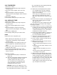
2. DISASSEMBLY INSTRUCTIONS 2.1 MECHANICAL PARTS 2.1.1 FRONT GRILLE Figure 1 1. Pull the inlet grille forward. 2. Remove the screw securing the Front Grille. (Fig. 3) 3. Push the grille up from the bottom and pull the top of the grille away from the case to lift the top tabs out of their slots. (Fig. 4) 4. Carefully position the grille, bottom first, and snap back into place. 5. Reposition the screw that secures the front grille Figure 2 2.1.2 CABINET 1. Disconnect the unit from the power source. 2.
2.2 AIR HANDLING PARTS Figure 6 2.2.1 AIR GUIDE UPPER 1. Disconnect the unit from the power source. 2. Remove the front grille. (Refer to Section 2.1.1) 3. Remove the cabinet. (Refer to Section 2.1.2) 4. Remove the control panel. (Refer to Section 2.1.3) 5. Remove 2 screws that secure the upper air guide to air guide lower. (See Figure 6) 6. Lift upper air guide upward. 7. Re-install by referring to the procedures above. Figure 7 2.2.2 ORIFICE, TURBO FAN AND FAN 1.
2.2.3 MOTOR Figure 10 1. Disconnect the unit from the power source. 2. Remove the front grille. (Refer to Section 2.1.1) 3. Remove the cabinet. (Refer to Section 2.1.2) 4. Remove the control panel. (Refer to Section 2.1.3) 5. Remove the upper air guide. (Refer to Section 2.2.1) 6. Remove the compressor, turbo fan, fan and shroud. (Refer to Section 2.2.2) 7. Remove 2 screws that secure the motor to the motor mount . (See Figure 10) 8. Remove the motor. 9. Re-install by referring to the procedures above.
2.3.2 COMPRESSOR Figure 14 1. Remove the front grille and cabinet. (Refer to Section 2.1) 2. Discharge the refrigerant by using a refrigerant recovery system. 3. Remove the overload protector. (Refer to Section 2.3.1) 4. After discharging the unit completely, unbrace the suction and discharge pipes at the compressor connections. 5. Remove 3 nuts which fasten the compressor. 6. Remove the compressor. 7. Re-install by referring to the removal procedure above. (See Figure 14) 2.3.3 CAPACITOR 1.
Figure 18 2.3.6 POWER CORD 1. Disconnect the unit from source of power. 2. Remove the front grille. (Refer to Section 2.1.1) 3. Remove the cabinet. (Refer to Section 2.1.2) 4. Remove a screw that secures control panel to base pan. (Refer to Section 2.1.3) 5. Pulls the control board toward you. 6. Disconnect the 2 receptacles and remove the grounding screw. 7. Remove a screw securing the clip with cord to the control panel. 8. Pull the power cord. 9. Re-install by referring to procedures above.
wise. This will keep oil from foaming and being drawn into the vacuum pump. 2.4.2 EVAPORATOR 1. Remove the cabinet. 2. Discharge the refrigerant by using a refrigerant recovery system. 3. Remove the upper air guide . (Refer to Section 2.2.1) 4. After discharging the refrigerant completely, unbraze the interconnecting tube at the condenser connections. 5. Remove the evaporator. 6. Re-install by referring to the procedures above. 2.4.3 CAPILLARY TUBE 1. Remove the cabinet. 2.
Equipment needed: Vacuum pump, charging cylinder, manifold gauge, brazing equipment, pinch-off tool capable of making a vapor proof seal, leak detector, tubing cutter, hand tools to remove components and service valve.
2.4.4 ELECTRICAL DATA Line Cord Plug Use Wall Receptacle Do not under any circumstances cut or remove the grounding prong from the plug. Power supply cord with 3-prong grounding plug Power Supply Use 15 AMP, time delay fuse, or circuit breaker. Standard 125V, 3-wire grounding receptacle rated 15A, 125V AC USE OF EXTENSION CORDS Because of potential safety hazards, we strongly discourage the use of an extension cord.
3.2 PIPING SYSTEM CONDENSER COILS FAN MOTOR CAPILLARY TUBE TURBO FAN EVAPORATOR COILS Following is a brief description of the important components and their function in what is called the refrigeration system. Reference should be made to Figure 32 to follow the refrigerating cycle and the flow of the refrigerant in the cooling cycle.
3.3 TROUBLESHOOTING GUIDE In general, possible trouble is classified in two kinds. The one is called Starting Failure which is caused by an electrical defect. The other is Ineffective Air Conditioning caused by a defect in the refrigeration circuit and improper application. Unit is running but cooling is ineffective. Ineffective Cooling Check cold air circulation for smooth flow. Check outdoor coil (heat exchanger) and fan operation. Dirty indoor coil (heat exchanger) Check for gas leakage.
Fails to Start Check of circuit breaker and fuse. Check voltage power source. Check control switch setting. Gas leakage of feeler bulb of thermostat. Check control switch. Compressor fails to start. Fan fails to start. Drop of power voltage. Improper thermostat setting Defect of compressor or capacitor. Loose terminal connection Capacitor check. Improper wiring Improper wiring. Defect of fan motor or capacitor. Irregular motor resistance (Ω) Irregular motor insulation (Ω) Replacement.
ROOM AIR CONDITIONER VOLTAGE LIMITS NAME PLATE RATING MINIMUM MAXIMUM 115V ± 10% 103.5V 126.5V COMPLAINT Fan motor will not run. CAUSE REMEDY No power Check voltage at outlet. Correct if none. Power supply cord Check voltage to electronic control board. If none, check power supply cord. Replace cord if circuit is open. Wire disconnected or connection loose Connect wire. Refer to wiring diagram for terminal identification. Repair or replace loose terminal.
COMPLAINT Fan motor noise. Compressor will not run, fan motor runs. CAUSE REMEDY Fan blade If cracked, out of balance, or partially missing, replace it. Blower wheel If cracked, out of balance, or partially missing, replace it. Loose set screw Tighten it. Worn bearings If knocking sounds continue when running replace the motor. If the motor hums or noise appears to be internal while running, replace motor. Voltage Check voltage. See the limits on the preceding page.
COMPLAINT Compressor cycles on overload. Insufficient cooling Excessive noise CAUSE REMEDY Fan motor If not running, determine the cause. Replace if required. Condenser air flow restriction Remove the cabinet, inspect the interior surface of the condenser. If restricted, clean carefully with a vacuum cleaner (do not damage fins) or brush. Clean the interior base before re-assembling.
4. CIRCUIT DIAGRAM POWER INPUT WH(BL) BK(BR) (Plain) GN/YL(GN) BK BL RD OR(BR) YL COMP. BK RD BL R S C OLP MAIN P.W.B ASM OR BK RD BL CN-DISP RY-HI CN-SYNC F H RY-MID CN-WORK GN/YL (GN) CAPACITOR C THERMISTOR CN-TH1 RY-LO MOTOR BK BL RD OR(BR) YL DISPLAY P.W.B ASM (Ribbed) WH SYNC MOTOR BK RY-SYNC ZNR RY-COMP 4 3 TRANS FORMER FUSE 250V/T2A (115V/T2A) 3854A20022K WIRING DIAGRAM LOCATION NO. PART NO.
5.
6. SERVICE PARTS LIST R: Service Parts N: Non Service Parts • CP05C10 CP05C10 LocNo FRIEDRICH DESCRIPTION 130410 67302921 Base Assy Single 130910 67303709 Cabinet Assy Single 135312 67306003 Grille Assy Front 135313 67304200 Grille Assy Inlet 147581 147582-1 67304600 67304501 Link Louver Vertical 2 ea.
MEMO —22—
MEMO —23—
Use Factory Certified Parts... FRIEDRICH AIR CONDITIONING CO. Visit our web site at www.friedrich.com Post Office Box 1540 • 4200 N. Pan Am Expressway • San Antonio, Texas 78295-1540 • (210) 357-4400 • FAX (210) 357-4490 CP05.