2002 HAZARDGARD® ROOM AIR CONDITIONER Models SH14J30B-A SH20J30B-A Service & Parts Manual AMERICA’S BEST AIR CONDITIONER HG2002 (02/02)
TABLE OF CONTENTS PAGE Specifications .................................................................................................................... Performance Data............................................................................................................. Component Operation & Testing ....................................................................................... Compressors ....................................................................................................
SH14J30B-A SH20J30B-A 14000/14000 19000/18800 E.E.R. - Btu/watt 8.0/8.0 8.5/8.5 Volts 230/208 230/208 60/1 60/1 7.8/8.5 9.9/10.8 1750/1750 2235/2210 15 20 Fan RPM 1095 1095 Evaporator Air CFM 375 425 Dehumidification-Pts./hr. 4.0 5.7 Width 25-15/16” 25-15/16” Height 15-15/16” 17-15/16” Depth 27-3/8” 27-3/8” Min. Ext. into Room 5-7/8” 5-7/8” Min. Ext to Outside 16-15/16” 16-15/16” Net Weight 129 Lbs. 177 Lbs. Shipping Weight 147 Lbs. 199 Lbs.
COMPONENT OPERATION AND TESTING WARNING DISCONNECT ELECTRICAL POWER TO THE UNIT BEFORE SERVICING OR TESTING COMPRESSORS COMPRESSOR WINDING TEST (See Figure 2.) Remove the compressor terminal box cover and disconnect the wires from the terminals. Using an ohmmeter, check continuity across the following: FIGURE 2 COMPRESSOR WINDING TEST Compressors are single phase, 208/230 volt. All compressor motors are permanent split capacitor type, using only a running capacitor across the start and run terminal.
GROUND TEST FAN MOTOR (Figure 4) Use an ohmmeter set on its highest scale. Touch one lead to the compressor body (clean point of contact, as a good connection is a must) and the other probe in turn to each compressor terminal. (See Figure 3.) If a reading is obtained, the compressor is grounded and must be replaced. A 230 volt single phase permanent split capacitor motor is used to drive the evaporator blower and condenser fan. A running capacitor is wired across the start and run terminals of the motor.
SYSTEM CONTROL SWITCH CAPACITOR – TEST (Figure 5) This switch is double pole, single throw. Check 1. Remove the capacitor from the unit. for continuity between terminals 2 and 3, and 5 2. Check for visual damage such as bulges, and 6. cracks, or leaks. 3. For dual rated capacitors, apply an ohmmeter lead to the common (C) terminal and the other probe to the compressor (HERM) terminal. A satisfactory capacitor will cause a deflection on the pointer, then gradually move back to infinity.
TEST Remove the wires from the thermostat. Turn the thermostat to its coldest position. Check to see if there is continuity between the two terminals. Turn the thermostat to its warmest position. Check continuity to see if the thermostat contacts open. Note: The temperature must be within the range listed to check the thermostat. Refer to the troubleshooting section in this manual for additional information on thermostat testing.
LOW AMBIENT BY–PASS VALVE The HazardGard unit is designed to operate at low outside ambient temperatures. This is accomplished by the use of a bypass valve installed in the refrigeration circuit. The valve is connected between the discharge line at the compressor and the suction process tube. The valve responds to suction pressure which, when reduced in the system, causes the valve to open and bypass hot gas from the high pressure side to the low pressure side of the system.
HERMETIC COMPONENT REPLACEMENT The following procedure applies when replacing components in the sealed refrigeration circuit or repairing refrigerant leaks. (Compressor, condenser, evaporator, capillary tube, refrigerant leaks, etc.) 10.Evacuate the system to an absolute holding pressure of 200 microns or less. NOTE: This procedure can be speeded up by the use of heat lamps, or by breaking the vacuum with refrigerant or dry nitrogen at 5,000 microns.
ROTARY COMPRESSOR SPECIAL TROUBLESHOOTING AND SERVICE REFRIGERANT CHARGE Basically, troubleshooting and servicing rotary compressors is the same as on the reciprocating compressor with only a few exceptions. 1. Because of the spinning motion of the rotary, the mounts are critical. If vibration is present, check the mounts carefully. 1. The refrigerant charge is extremely critical. Measure the charge carefully and as exactly as possible to the nameplate charge. 2.
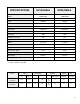
TROUBLESHOOTING PROBLEM Unit does not run. PROBLEM Evaporator coil freezes up. POSSIBLE CAUSE Power disconnected. System switch in “Off” position. Branch circuit fuse blown or circuit breaker tripped. Inoperative system switch. Loose or disconnected wiring at switch. Inoperative switch (On-Off). POSSIBLE CAUSE Dirty Filter. Restricted air flow. Inoperative thermostat. Short of refrigerant. Partially restricted capillary. Inoperative fan motor. PROBLEM POSSIBLE CAUSE Excessive heat load.
TROUBLESHOOTING (Continued) PROBLEM POSSIBLE CAUSE Compressor attempts to start Compressor before system pressures are attempts to equalized. start, or runs Low or fluctuating voltage. for short periods only. Incorrect wiring. Cycles on Shorted or incorrect capacitor. overload. Restricted or low air flow through condenser coil. Compressor running abnormally hot. Overload opens too soon. PROBLEM POSSIBLE CAUSE Thermostat contacts not closing. Compressor does not start - fan motor runs.
TROUBLESHOOTING (Continued) PROBLEM POSSIBLE CAUSE Switch (On-Off) Selector Switch Relay does not cut fan motor off. PROBLEM Noisy and/or vibration. POSSIBLE CAUSE Poor installation. Fan blade striking chassis. Compressor vibrating. Loose cabinet parts, improperly mounted components, tubing rubbing. PROBLEM POSSIBLE CAUSE Evaporator drain pan Water leaks into overflowing. room. Condensation forming on bottom of base pan. Water dripping from discharge air grilles.
WIRING DIAGRAM FOR SH14J30B-A & SH20J30B-A 14
HazardGard Cabinet Parts 15
HazardGard Chassis Parts 16
HAZARDGARD PARTS LIST REF. PART NO. DESCRIPTION APPLICATION ELECTRICAL PARTS 1 1 2 2 3 4 5 * * 6 7 7 8 * * * 611-935-49 611-935-50 618-714-26 618-714-27 617-682-00 613-892-00 609-353-00 618-297-00 611-088-00 618-225-02 610-805-46 610-805-46 618-298-00 613-891-00 618-213-07 618-208-01 Compressor, Tecumseh, 230/208V; 60 Hz 1 Ph, Model AWG5515EXN ...................... Compressor, Tecumseh, 230/208 V; 60 Hz 1 Ph, Model AWG5519EXN ..................... Motor, Fan 1/8 HP ..................................
HAZARDGARD PARTS LIST REF. PART NO. DESCRIPTION APPLICATION CHASSIS PARTS (Cont.
HAZARDGARD PARTS LIST REF. PART NO. DESCRIPTION APPLICATION CHASSIS PARTS (Cont.) * * * * 36 36 37 37 * 38 38 * * 39 40 41 41 42 * * * * * * * * 43 * 618-092-00 618-062-00 618-063-00 618-063-01 618-032-03 618-046-00 618-089-00 618-111-00 618-199-00 602-944-08 602-944-09 611-050-04 611-050-05 611-095-03 618-197-01 618-198-01 618-198-03 606-103-03 608-460-16 617-173-01 618-116-20 618-116-21 618-139-00 618-118-00 618-118-01 618-141-01 600-733-00 Not Shown Lever, Fresh Air & Exhaust .....................
Use Factory Certified Parts... Friedrich Air Conditioning Co. 4200 North Pan Am Expressway P.O. Box 1540, San Antonio, Texas 78295-1540, USA Tel. (210) 357/4400 Fax: (210) 357/4480 HG2002 (02/02) Printed in the U.S.