
Service & Parts Manual
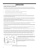
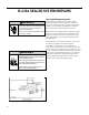
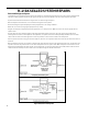
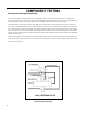
Table Of Contents
- _GoBack
- INTRODUCTION
- SPECIFICATIONS
- OPERATION
- R-410A SEALED SYSTEM REPAIR
- COMPONENT TESTING
- Hermetic Components Check
- Reversing valve description and operation
- Testing The Reversing Valve Solenoid Coil
- Checking The Reversing Valve
- Replace The Reversing Valve
- Touch Test Chart : To Service Reversing Valves
- Compressor Checks
- Compressor Replacement
- Compressor Replacement -Special Procedure in Case of Compressor Burnout
- Fan Motor
- Capacitors
- TROUBLESHOOTING
- WIRING DIAGRAMS
- PARTS CATALOG
- Unifit Models: UET14A33A
- Unifit Models: UET08A11A UET10A33A UET12A33A
- Unifit Models: UCT12A30, UCT14A30A
- Unifit Models: UCT08A10A UCT10A10A UCT12A10A UCT10A30A
- Chill Premier Models: CCF10A10A CCF12A10A
- Chill Premier Models: CCF05A10A CCF06A10A CCF08A10A
- Chill Premier Models: CEW24B33A
- Chill Premier Models: CEW18B33A
- Chill Premier Models: CEW08B11A, CEW12B33A
- Chill Premier Models: CEW08B11A, CEW12B33A
- Chill Premier Models: CEW08B11A, CEW12B33A
- Chill Premier Models: CCW24B30A
- Chill Premier Models: CCW24B30A
- Chill Premier Models: CCW15B10A CCW18B30A
- Chill Premier Models: CCW06B10A CCW08B10A CCW10B10A CCW12B10A
- Available Accessories

21 PB
OPERATION
Refrigeration Sequence Of Operation
A good understanding of the basic operation of the refrigeration system is essential for the service technician. Without this
understanding, accurate troubleshooting of refrigeration system problems will be more difcult and time consuming, if not (in
some cases) entirely impossible. The refrigeration system uses four basic principles (laws) in its operation they are as follows:
1. “Heat always ows from a warmer body to a cooler body.”
2. “Heat must be added to or removed from a substance before a change in state can occur”
3. “Flow is always from a higher pressure area to a lower pressure area.”
4. “The temperature at which a liquid or gas changes state is dependent upon the pressure.”
The refrigeration cycle begins at the compressor. Starting the compressor creates a low pressure in the suction line which
draws refrigerant gas (vapor) into the compressor. The compressor then “compresses” this refrigerant vapor, raising its
pressure and its (heat intensity) temperature.
The refrigerant leaves the compressor through the discharge Line as a hot High pressure gas (vapor). The refrigerant enters
the condenser coil where it gives up some of its heat. The condenser fan moving air across the coil’s nned surface facilitates
the transfer of heat from the refrigerant to the relatively cooler outdoor air.
When a sufcient quantity of heat has been removed from the refrigerant gas (vapor), the refrigerant will “condense” (i.e.
change to a liquid). Once the refrigerant has been condensed (changed) to a liquid it is cooled even further by the air that
continues to ow across the condenser coil.
The design determines at exactly what point (in the condenser) the change of state (i.e. gas to a liquid) takes place. In all cases,
however, the refrigerant must be totally condensed (changed) to a Liquid before leaving the condenser coil.
The refrigerant leaves the condenser Coil through the liquid line as a warm high pressure liquid. It next will pass through the
refrigerant drier (if equipped). It is the function of the drier to trap any moisture present in the system, contaminants, and large
particulate matter.
The liquid refrigerant next enters the metering device. The metering device is a capillary tube. The purpose of the metering
device is to “meter” (i.e. control or measure) the quantity of refrigerant entering the evaporator coil.
In the case of the capillary tube this is accomplished (by design) through size (and length) of device, and the pressure difference
present across the device.
Since the evaporator coil is under a lower pressure (due to the suction created by the compressor) than the liquid line, the
liquid refrigerant leaves the metering device entering the evaporator coil. As it enters the evaporator coil, the larger area and
lower pressure allows the refrigerant to expand and lower its temperature (heat intensity). This expansion is often referred
to as “boiling” or atomizing. Since the unit’s blower is moving indoor air across the nned surface of the evaporator coil, the
expanding refrigerant absorbs some of that heat. This results in a lowering of the indoor air temperature, or cooling.
The expansion and absorbing of heat cause the liquid refrigerant to evaporate (i.e. change to a gas). Once the refrigerant has
been evaporated (changed to a gas), it is heated even further by the air that continues to ow across the evaporator coil.
The particular system design determines at exactly what point (in the
evaporator) the change of state (i.e. liquid to a gas) takes place. In all
cases, however, the refrigerant must be totally evaporated (changed)
to a gas before leaving the evaporator coil.
The low pressure (suction) created by the compressor causes the
refrigerant to leave the evaporator through the suction line as a cool
low pressure vapor. The refrigerant then returns to the compressor,
where the cycle is repeated.
Suction
Line
Evaporator
Coil
Metering
Device
Refrigerant
Strainer
Discharge
Line
Condenser
Coil
Compressor
Refrigerant Drier
Liquid
Line
Figure 341 (Refrigeration Sequence Of Operation)