Service/ Parts Manual RoomAir Conditioners Chill Premiere Series Models Fixed chassis, cool only CCF05A10A, CCF06A10A, CCF08A10A, CCF10A10A CCF12A10A Slide out chassis, cool only CCW06B10A, CCW08B10A, CCW10B10A, CCW12B10A CCW15B10A, CCW18B30A, CCW24B30A Slide out chassis, heat & cool CEW08B11A, CEW12B33A, CEW18B33A, CEW24B33A Unifit Series Models Cool Only UCT08A10A, UCT10A10A, UCT10A30A, UCT10A30B,UCT12A10A, UCT12A30A, UCT14A30A, UCT14A30B Cool with Electric Heat UET08A11A, UET10A33A, UET12A33A, UET14A33
TABLE OF CONTENTS INTRODUCTION 3 IMPORTANT SAFETY INFORMATION 3 PERSONAL INJURY OR DEATH HAZARDS 4 SPECIFICATIONS 7 Electrical Data 9 Product Dimensions 11 OPERATION 12 Remote Control 12 Control Panel 13 Sequence of Operation 15 R-410A SEALED SYSTEM REPAIR Refrigerant Charging Undercharged Refrigerant Systems Overcharged Refrigerant Systems Restricted Refrigerant System Sealed System Method of Charging/ Repairs 22 23 24 25 26 27 COMPONENT TESTING 28 Hermetic Components Check 28 Compressor
INTRODUCTION IMPORTANT SAFETY INFORMATION The information in this manual is intended for use by a qualified technician who is familiar with the safety procedures required for installation and repair, and who is equipped with the proper tools and test instruments required to service this product.
INTRODUCTION PERSONAL INJURY OR DEATH HAZARDS SAFETY FIRST WARNING Do not remove, disable or bypass this unit’s safety devices. Doing so may cause fire, injuries, or death. AVERTISSEMENT Ne pas supprime, désactiver ou contourner cette l´unité des dispositifs de sécurité, faire vous risqueriez de provoquer le feu, les blessures ou la mort. ADVERTENCIA No eliminar, desactivar o pasar por alto los dispositivos de seguridad de la unidad. Si lo hace podría producirse fuego, lesiones o muerte.
INTRODUCTION PERSONAL INJURY OR DEATH HAZARDS 5 • REFRIGERATION SYSTEM REPAIR HAZARDS: • Use approved standard refrigerant recovering procedures and equipment to relieve high pressure before opening system for repair. • Do not allow liquid refrigerant to contact skin. Direct contact with liquid refrigerant can result in minor to moderate injury. • Be extremely careful when using an oxy-acetylene torch. Direct contact with the torch’s flame or hot surfaces can cause serious burns.
INTRODUCTION This service manual is designed to be used in conjunction with the installation and operation manuals provided with each air conditioning system. This service manual was written to assist the professional service technician to quickly and accurately diagnose and repair malfunctions. Installation procedures are not given in this manual. They are given in the Installation/Operation manual which can be aquired on the Friedrich website.
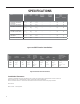
SPECIFICATIONS Model Cooling Heating Volts Cooling Cooling Heating Heating Btu Btu Rated Amps Watts Amps Watts EER CEER Moisture Refrigerant Removal- Refrigerant CFM Sleeve Charge Weight Net./ Pints/HR Ship lbs. FIXED CHASSIS, COOL ONLY (WINDOW INSTALLATION ONLY) CCF05A10A 5200 — 115 4.3 459 — — 12.1 12.1 1.0 R410A 12.35 141 44/51 CCF06A10A 6000 — 115 4.3 492 — — 12.1 12.1 0.9 R410A 13.76 141 44/51 CCF08A10A 8000 — 115 5.8 661 — — 12.1 12.
SPECIFICATIONS Model Height Inches Width Inches Depth Inches Minimum Extension Into Room Inches Minimum Extension Outside Inches Window Width Inches Minimum* Maximum CCF05A10A, CCF06A10A, CCF08A10A 13 3/8 18 5/8 15 5/8 — — 23 36 CCF10A10A, CCF12A10A 15 1/8 19 7/8 21 1/2 — — 26 36 14 5/8 19 3/4 21 1/2 — — 23 36 CEW08B11A, CCW10B10A, CCW12B10A, CEW12B33A, 15 1/8 19 3/4 24 — — 26 36 CCW15B10A, CCW18B30A, CEW18B33A 17 7/8 23 5/8 25 3/8 — — 28 41 CCW24B30A, CEW24B33
SPECIFICATIONS Electrical Data WARNING ELECTRIC SHOCK HAZARD Turn off electric power before service or installation. All electrical connections and wiring MUST be the National Electrical Code and all local codes which have jurisdiction. NOTICE FIRE HAZARD electically unsafe conditions which could cause moderate or serious property damage. Read, understand and follow the above warning. Failure to do so can result in personal injury or death.
SPECIFICATIONS Electrical Data WARNING Electrical Shock Hazard Make sure your electrical receptacle has the same configuration as your air conditioner’s plug. If different, consult a Licensed Electrician. Do not use plug adapters. Do not use an extension cord. Do not remove ground prong.Always plug into a grounded 3 prong outlet. Failure to follow these instructions can result in death, fire, or electrical shock. Wire Size - Use ONLY wiring size recommended for single outlet branch circuit.
Product Dimensions SPECIFICATIONS C B A Model A “(inches) B “(inches) C “(inches) CCF05A10A, CCF06A10A, CCF08A10A 18 5/8 13 3/8 15 5/8 CCF10A10A, CCF12A10A 19 3/4 15 1/8 21 1/2 CCW06B10A, CCW08B10A 19 3/4 14 5/8 21 1/2 CEW08B11A, CCW10B10A, CCW12B10A, CEW12B33A, 19 3/4 15 1/8 24 24 7/32 14 17/32 20 9/32 Chill® Premier CCW15B10A, CCW18B30A, CEW18B33A CCW24B30A, CEW24B33A UNI-FIT® All Models Figure 205 11
OPERATION Remote Control 1. Power: Turn the air conditioner on and off. This button will clear the TIMER setting. 2. MODE: Press the button to select the mode of operation, AUTO, COOL, DRY, FAN ONLY, HEAT. Note: The HEAT mode is only for some heating models. If you do not need it, press the MODE button for more than 5 seconds to delete the HEAT function, and the COOL mode will be selected automatically.
OPERATION Control Panel USING YOUR AIR CONDITIONER Electronic Control Panel & Remote Control NOTE: This display always shows the room temperature in Fan Mode except when setting the Timer. For Cooling model I TEMP/HR. + :�: :1 :;: ·1 l 0 '? '" MONEY > 2 3 MODE TIM R : 9 8 For Heating model 7 1 6 5 4 I TEMP/HR.
Control Panel OPERATION or HEAT mode and 14
OPERATION Sequence of Operation Main function NOTES: RT------Room Temperature. IC------Indoor CoilTemperature. ST------indoor Set Temperature. OC---Outdoor Coil Temperature. CRT---Compensated Room Temperature 1. Cooling mode In the cooling mode, COOL indicator is ON, the set temperature and fan speed could be changed or adjusted. a. When RT-ST≥ 1.8°F the compressor operates if there is not any protection or failure happened. b. When RT-ST< 1.
OPERATION Sequence of Operation 2. Dry mode While selected to Dry mode, AC works at set temperature to 44.6°F for 3 minutes. After that the set temperature change to be RT 3.6°F, the compressor works as cooling mode, and indoor fan motor operates at low speed. The fan speed can not be changed while in dry mode, but the air direction can be adjusted. 3. I FEEL Mode 3.
OPERATION Sequence of Operation 4. Heating mode When in heating operation mode, the set temperature, fan speed and air direction can be adjusted, compressor does not operate, but electrical heater works, and indoor fan motor starts up 10s later. a ST-RT≥ 1.8°F electrical heater operates b ST-RT < 1.8°F electrical heater stops. c 1.8°F ≤ST-RT < 1.8° electrical heater keeps the original works status . Indoor fan motor control 4.1 Indoor fan motor can be controlled by Auto, Low, Med or High speed. 4.
OPERATION Sequence of Operation a) The indoor fan runs at the set speed when processing sleep mode, after the 1st change, unit runs at low speed, and after the 2nd change, unit runs at low-low speed ( if AC without low-low speed, it runs at low speed instead). 10 hours later AC quits from sleep mode and runs at former set fan speed . b) In SLEEP mode, the vane works according to the preset, after the first change, vane blade works at cold air prevention angle.
Sequence of Operation OPERATION a) The indoor fan motor runs for 1 min according to the set speed continuously, and then stops. b) The indoor fan keeps the stopping status in the following 10 min if RT meets the requirement of compressor stopping work. c) After 10 min, the indoor fan motor runs for 20 seconds and lets the indoor air flow through the evaporator. d) The indoor fan works as step b) and c) circularly.
Sequence of Operation OPERATION Protection / Failure code 1 Anti-frozen protection for indoor evaporator: If IPT≤32°F for continuous 3min, compressor shut off, fan motor keeps former operation; 3min later, if IPT≥50°F, compressor start up operation and fan motor keeps the former running status. 2 SENSOR error protection When sensor short circuit or broken, Room Temperature failure shows E1, and Coil Temperature failure shows E2.
OPERATION Refrigeration Sequence Of Operation A good understanding of the basic operation of the refrigeration system is essential for the service technician. Without this understanding, accurate troubleshooting of refrigeration system problems will be more difficult and time consuming, if not (in some cases) entirely impossible. The refrigeration system uses four basic principles (laws) in its operation they are as follows: 1. “Heat always flows from a warmer body to a cooler body.” 2.
R-410A SEALED SYSTEM REPAIR WARNING Refrigeration system under high pressure O service this equipment. R410A systems operate at higher pressures than R22 equipment. Appropriate safe service and handling practicces must be used. Only use gauge sets designed for use with R410A. Do not use standard R22 gauge sets. The following is a list of important considerations when working with R-410A equipment 1. R-410A pressure is approximately 60% higher than R-22 pressure. 2.
R-410A SEALED SYSTEM REPAIRS WARNING RISK OF ELECTRIC SHOCK Unplug and/or disconnect all electrical power to the unit before performing inspections, maintenances or service. Failure to do so could result in electric shock, serious injury or death. WARNING HIGH PRESSURE HAZARD Sealed Refrigeration System contains refrigerant and oil under high pressure. Proper safety procedures must be followed, and proper protective clothing must be worn when working with refrigerants.
R-410A SEALED SYSTEM REPAIRS Undercharged Refrigerant Systems WARNING RISK OF ELECTRIC SHOCK Unplug and/or disconnect all electrical power to the unit before performing inspections, maintenances or service. Failure to do so could result in electric shock, serious injury or death. WARNING HIGH PRESSURE HAZARD Sealed Refrigeration System contains refrigerant and oil under high pressure. Proper safety procedures must be followed, and proper protective clothing must be worn when working with refrigerants.
R-410A SEALED SYSTEM REPAIRS Overcharged Refrigerant Systems WARNING RISK OF ELECTRIC SHOCK Unplug and/or disconnect all electrical power to the unit before performing inspections, maintenances or service. Failure to do so could result in electric shock, serious injury or death. WARNING HIGH PRESSURE HAZARD Sealed Refrigeration System contains refrigerant and oil under high pressure. Proper safety procedures must be followed, and proper protective clothing must be worn when working with refrigerants.
R-410A SEALED SYSTEM REPAIRS Restricted Refrigerant System Troubleshooting a restricted refrigerant system can be difficult. The following procedures are the more common problems and solutions to these problems. There are two types of refrigerant restrictions: Partial restrictions and complete restrictions. A partial restriction allows some of the refrigerant to circulate through the system. With a complete restriction there is no circulation of refrigerant in the system.
R-410A SEALED SYSTEM REPAIRS Sealed System Method of Charging/ Repairs WARNING CAUTION BURN HAZARD Proper safety procedures must be followed, and proper protective clothing must be worn when working with a torch. FREEZE HAZARD Proper safety procedures must be followed, and proper protective clothing must be worn when working with liquid refrigerant. Failure to follow these procedures could result in moderate or serious injury.
COMPONENT TESTING Hermetic Components Check WARNING WARNING BURN HAZARD Proper safety procedures must be followed, and proper protective clothing must be worn when working with a torch. CUT/SEVER HAZARD Be careful with the sharp edges and corners. Wear protective clothing and gloves, etc. Failure to follow these procedures could result in moderate or serious injury. Failure to do so could result in serious injury.
Compressor Checks COMPONENT TESTING WARNING ELECTRIC SHOCK HAZARD Turn off electric power before installation. WARNING service or All electrical connections and wiring MUST be the National Electrical Code and all local codes which have jurisdiction. Failure to do so can result in personal injury or death. BURN HAZARD Proper safety procedures must be followed, and proper protective clothing must be worn when working with a torch.
Compressor Checks COMPONENT TESTING WARNING ELECTRIC SHOCK HAZARD Turn off electric power before service or installation. Extreme care must be used, if it becomes necessary to work on equipment with power applied. Failure to do so could result in serious injury or death. WARNING HIGH PRESSURE HAZARD Sealed Refrigeration System contains refrigerant and oil under high pressure. Proper safety procedures must be followed, and proper protective clothing must be worn when working with refrigerants.
Compressor Replacement COMPONENT TESTING 1. Be certain to perform all necessary electrical and refrigeration tests to be sure the compressor is actually defective before replacing. WARNING ELECTRIC SHOCK HAZARD Turn off electric power before service or installation. Extreme care must be used, if it becomes necessary to work on equipment with power applied. Failure to do so could result in serious injury or death.
COMPONENT TESTING Compressor Replacement -Special Procedure in Case of Compressor Burnout WARNING HIGH PRESSURE HAZARD Sealed Refrigeration System contains refrigerant and oil under high pressure. Proper safety procedures must be followed, and proper protective clothing must be worn when working with refrigerants. Failure to follow these procedures could result in serious injury or death. 1. Recover all refrigerant and oil from the system. 2.
COMPONENTS TESTING Fan Motor A single phase permanent split capacitor motor is used to drive the evaporator blower and condenser fan. A selfresetting overload is located inside the motor to protect against high temperature and high amperage conditions. WARNING Figure 23 Blower/Fan Motor ELECTRIC SHOCK HAZARD Turn off electric power before service or installation. Extreme care must be used, if it becomes necessary to work on equipment with power applied.
COMPONENTS TESTING Heating Element WARNING ELECTRIC SHOCK HAZARD Turn off electric power before service or installation. Heating Element Example All electrical connections and wiring MUST be the National Electrical Code and all local codes which have jurisdiction. Failure to do so can result in personal injury or death. All electric heat models are equipped with a heating element . The models are equipped with either a 1.32 Kw or a 3.5 Kw element. The heating element contains a fuse link.
Check Thermistors TROUBLESHOOTING 1. Gain Acces to Main PCB (logic) board 2. Using a multi meter ohm across applicaple pins for the sensor you are checking. 3. All Sensors are 5k. Refer to thermistor chart on following for resistance and temperature deviation. 4. Replace sensor if open or if resistance values deviate by more than 10% of the listed values.
TROUBLESHOOTING Check Thermistors -Resistance Table of Thermistors (5K) 36 Temp Resis Temp Resis Temp Resis Temp Resis Temp Resis -33 130100 7 34252 47 10785 57 8275 97 3119 -32 125518 8 33209 48 10499 58 8063 98 3048 -31 121114 9 32202 49 10221 59 7857 99 2980 -30 116881 10 31228 50 9952 60 7657 100 2913 -29 112811 11 30288 51 9690 61 7462 101 2848 -28 108898 12 29378 52 9437 62 7273 102 2785 -27 105131 13 28499 53 9190 63 7090
TROUBLESHOOTING ROOM AIR CONDITIONER UNIT PERFORMANCE TEST DATA SHEET JOB NAME______________________ TECH’S NAME_________________________ DATE___________ MODEL#_______________ SERIAL #______________________ CHECK THE INSTALLATION ACCEPTABLE NOT ACCEPTABLE YES NO IS A CHASIS GASKET INSTALLED? _____ ____ IS THE FRESH / EXHAUST AIR VENT OPEN? _____ ____ IS A FRIEDRICH SLEEVE INSTALLED? _____ ____ IS A FRIEDRICH OUTDOOR GRILLE INSTALLED? _____ ____ IS MAINTENANCE BEING PERFORMED? ____
TROUBLESHOOTING Product Does Not Operate At All Product does not operate at all. Power supply voltage check Power input voltage on driving load terminal.
TROUBLESHOOTING Indoor Fan Does Not Operate At All Indoor fan does not operate at all.
TROUBLESHOOTING CompressorCompressor Or Outdoor Fan Does Not Operate At All or outdoor fan does not operate at all. Re-input after power of f Set the desired temperature of remote controller to be lower by 2°C or over than room temperature, and start the cooling operation. Does not operate at all. Repeat running/stopping at a short time period. Temperature sensor open/short check Thermistor and evaporator surface contact check.Clearance is needed (5mm).
Display E1 or E2 TROUBLESHOOTING Display E1 and E2 Connector contact Check the wire connection of indoor temperature sensor assembly.
Chill Premier CCF WIRING DIAGRAMS Models: CCF05A10A CCF06A10A CCF08A10A CCF10A10A CCF12A10A E Figure 801 42
Chill Premier CCW WIRING DIAGRAMS Models: CCW06B10A .
Chill Premier CCW WIRING DIAGRAMS CCW08B10A odels: Models: CCW10B10A.CCW12B10A.
Chill Premier WIRING DIAGRAMS CCW10B10A, CCW12B10A, CCW15B10A, CCW18B30A Models: CCW10B10A.CCW12B10A.
Chill Premier CEW WIRING DIAGRAMS CEW08B11A Figure 805 46
Chill Premier CEW WIRING DIAGRAMS CEW12B33A, CEW18B33A Figure 806 47
Chill Premier CEW WIRING DIAGRAMS CEW24B33A Figure 807 48
WIRING DIAGRAMS Unifit UCT08A10A, UCT10A10A, UCT12A10A, UCT10A30A, UCT12A30A, UCT14A30A Models: UCT08A10A UCT10A10A UCT12A10A UCT10A30A UCT12A30A UCT14A30A E Models: UET10A33A UET12A33A UET14A33A UET08A11A Figure 808 49
WIRING DIAGRAMS Unifit UET10A33A, UET12A33A, UET14A33A, UET08A11A E Models: UET10A33A UET12A33A UET14A33A UET08A11A E Figure 809 50
PARTS CATALOG Chill Premier Models: CCW06B10A CCW08B10A CCW10B10A CCW12B10A 51 FIgure 901
PARTS CATALOG Chill Premier Models: CCW06B10A CCW08B10A CCW10B10A CCW12B10A 52 FIgure 901 ITEM PART NUMBER PART DESCRIPTION USED ON MODEL QTY 1 68000163 41106-003745_UI - Front Panel Assembly CCW06B10A, CCW08B10A,CCW10B10A 1 1A 68000264 41106-003738_UI - Front Panel Assembly CCW12B10A 1 1.6 68000175 41507-000136 - Air Filter CCW06B10A, CCW08B10A, CCW10B10A, CCW12B10A 1 2 68000181 41505-000230 - Electrical Box Assembly CCW06B10A, CCW08B10A, CCW10B10A, CCW12B10A 1 2.
PARTS CATALOG Chill Premier Models: CCW06B10A CCW08B10A CCW10B10A CCW12B10A ITEM PART NUMBER PART DESCRIPTION USED ON MODEL 17 68000230 92014-000599 - Compressor CCW06B10A 1 17A 68000254 92014-000259 - Compressor CCW08B10A 1 17B 68000262 92014-000305 - Compressor CCW10B10A 1 17C 68000270 92014-000262 - Compressor CCW12B10A 1 18 68000231 41502-000042 - Base CCW06B10A, CCW08B10A, CCW10B10A, CCW12B10A 1 -19 68000232 RT/ IPT Sensor Pack 5k CCW10B10A, CCW12B10A 1 -19 68000021
PARTS CATALOG Chill Premier Models: CCW15B10A CCW18B30A 54 FIgure 902
PARTS CATALOG Chill Premier Models: CCW15B10A CCW18B30A ITEM 55 PART NUMBER PART DESCRIPTION USED ON MODEL FIgure 902 QTY 1 68000273 41106-003518_UW - Front Panel Assembly CCW15B10A, CCW18B30A 1 1.
PARTS CATALOG Chill Premier Models: CCW15B10A CCW18B30A ITEM PART NUMBER PART DESCRIPTION USED ON MODEL QTY 27 68000306 92011-003343 - Evaporator CCW15B10A 1 27A 68000323 92011-003349 - Evaporator CCW18B30A 1 27.1 68000307 92007-001542 - Capillary Assembly CCW15B10A 1 27.1A 68000324 92007-001525 - Capillary Assembly CCW18B30A 1 27.2 68000308 92006-000181 - Discharge Pipe CCW15B10A 1 27.
PARTS CATALOG Chill Premier Models: CCW24B30A 57 FIgure 903
PARTS CATALOG Chill Premier Models: CCW24B30A 58 FIgure 903
PARTS CATALOG Chill Premier Models: CCW24B30A ITEM 59 FIgure 903 PART NUMBER PART DESCRIPTION USED ON MODEL QTY 1 68000332 41106-003519_UW - Front Panel Assembly CCW24B30A 1 1.2 68000334 41507-000137 - Air Filter CCW24B30A 1 2 68000339 41205-000164 - Left Supporter CCW24B30A 1 3 68000340 41505-000229 - Electrical Box Assembly CCW24B30A 1 3.1 68000341 41507-000033 - Control Box panel CCW24B30A 1 3.2 68000342 31502-000026 - Display PCB CCW24B30A 1 3.
PARTS CATALOG Chill Premier Models: CCW24B30A ITEM PART NUMBER PART DESCRIPTION USED ON MODEL 19 68000360 41504-000150_UW - Front Vortex Shell CCW24B30A 1 20 68000361 92011-003350 - Evaporator CCW24B30A 1 21 68000305 41605-000011 - Sensor Holder CCW24B30A 1 22 68000362 92014-000276 - Compressor CCW24B30A 1 23 68000363 41504-000098 - Water drainage pan CCW24B30A 1 24 68000301 41214-000856 - Pipe Cover (twoway) CCW24B30A 1 25 68000300 41214-000857 - Pipe Cover (fourway) C
PARTS CATALOG Chill Premier Models: CEW08B11A, CEW12B33A 61 FIgure 904
PARTS CATALOG Chill Premier Models: CEW08B11A, CEW12B33A ITEM 62 FIgure 904 PART NUMBER PART DESCRIPTION USED ON MODEL QTY 1 68000449 Front Panel Assembly ALL 1 1.1 68000165 Intake grille ALL 1 1.2 68000167 swing rod ALL 1 1.3 68000169 Leading Flow Circle ALL 1 1.4 68000171 Louver ALL 1 1.5 68000173 Louver Connecter ALL 1 1.6 68000175 Air Filter ALL 1 1.7 68000177 Front Panel ALL 1 1.
PARTS CATALOG Chill Premier Models: CEW08B11A, CEW12B33A ITEM PART NUMBER PART DESCRIPTION USED ON MODEL 13 68000250 Back Surround Plate ALL 1 14 68000227 Fan Motor CEW08B11A 1 14 68000459 Fan Motor CEW12B33A 1 15 68000453 Centrifugal Fan ALL 1 16 68000229 Water drainage pan ALL 1 17 68000254 Compressor CEW08B11A 1 17 68000460 Compressor CEW12B33A 1 18 68000454 Base ALL 1 -19 68000232 RT/ IPT SENSOR PACK 5K ALL 1 -20 68000315 Display PCB ALL 1 -24 6800
PARTS CATALOG Chill Premier Models: CEW18B33A 64 FIgure 905
PARTS CATALOG Chill Premier Models: CEW18B33A ITEM 65 FIgure 905 PART NUMBER PART DESCRIPTION USED ON MODEL QTY 1 68000273 41106-003518 - Front Panel Assembly CEW18B33A 1 1.1 68000274 41607-000080 - Intake grille CEW18B33A 1 1.2 68000167 41507-000106 - swing rod CEW18B33A 1 1.3 68000275 41507-000126 - Leading Flow Circle CEW18B33A 1 1.4 68000276 42008-000095 - Air Filter CEW18B33A 1 1.5 68000277 41607-000059 - Front Panel CEW18B33A 1 1.
PARTS CATALOG Chill Premier Models: CEW18B33A 66 FIgure 905 ITEM PART NUMBER PART DESCRIPTION USED ON MODEL QTY 21 68000301 41214-000856 - Pipe Cover (twoway) CEW18B33A 1 22 68000420 41602-000022 - Base CEW18B33A 1 23 68000321 92014-000275 - Compressor CEW18B33A 1 24 68000304 22007-000280 - Compressor wire CEW18B33A 1 25 68000322 42001-000058 - Cable Clamp CEW18B33A 1 26 68000305 41605-000011 - Sensor Holder CEW18B33A 1 27 68000323 92011-003349 - Evaporator CEW18B33
PARTS CATALOG Chill Premier Models: CEW18B33A ITEM PART NUMBER PART DESCRIPTION USED ON MODEL -49 68000434 50209-100009 - gasket(inner diameter 4.3×t1.0) CEW18B33A 1 -50 68000435 51307-100006 - screw(ST4.2×12) CEW18B33A 1 -51 68000436 51314-100035 - screw(ST4.8×16F-H) CEW18B33A 1 -52 68000437 50704-100001 - bolt(M5×13) CEW18B33A 1 -53 68000438 50610-100019 - screw(M5) CEW18B33A 1 -54 68000439 51307-100005 - screw(ST4.
PARTS CATALOG Chill Premier Models: CEW24B33A 68 FIgure 906
PARTS CATALOG Chill Premier Models: CEW24B33A 69 FIgure 906
PARTS CATALOG Chill Premier Models: CEW24B33A ITEM 70 PART NUMBER PART DESCRIPTION USED ON MODEL FIgure 906 QTY 1 68000441 41106-003887 - Front Panel Assembly CEW24B33A 1 1.1 68000333 41507-000055 - Intake grille CEW24B33A 1 1.2 68000334 41507-000137 - Air Filter CEW24B33A 1 1.3 68000167 41507-000106 - swing rod CEW24B33A 1 1.4 68000335 41507-000117 - Leading Flow Circle CEW24B33A 1 1.5 68000336 41507-000093 - Louver CEW24B33A 1 1.
ITEM PART NUMBER PART DESCRIPTION USED ON MODEL 15 68000356 41509-000036 - Right Adjustable shade rail CEW24B33A 1 16 68000357 41504-000037 - Partition plate CEW24B33A 1 17 68000443 41304-000070 - Back Vortex Shell CEW24B33A 1 18 68000419 41503-000012 - Centrifugal Fan CEW24B33A 1 19 68000444 41504-000090 - Front Vortex Shell(UP) CEW24B33A 1 20 68000361 92011-003350 - Evaporator CEW24B33A 1 21 68000305 41605-000011 - Sensor Holder CEW24B33A 1 22 68000362 92014-000276
PARTS CATALOG Chill Premier Models: CCF05A10A CCF06A10A CCF08A10A 72 FIgure 907
PARTS CATALOG Chill Premier Models: CCF05A10A CCF06A10A CCF08A10A 73 FIgure 907 ITEM PART NUMBER PART DESCRIPTION USED ON MODEL QTY 1 68000216 210826698 - Base CCF05A10A, CCF06A10A 1 1A 68000145 210826701 - Base CCF08A10A 1 2 68000218 210755572 - Front Panel Assembly CCF05A10A, CCF06A10A, CCF08A10A 1 3 68000014 210736640A - Air Filter CCF05A10A, CCF06A10A, CCF08A10A 1 4 68000008 210755573 - Leading Flow Circle CCF05A10A, CCF06A10A, CCF08A10A 1 5 68000118 211241456 - Evapo
PARTS CATALOG Chill Premier Models: CCF05A10A CCF06A10A CCF08A10A ITEM PART NUMBER PART DESCRIPTION USED ON MODEL 16 68000018 210736633 - Propeller Fan CCF05A10A, CCF06A10A, CCF08A10A 1 17 68000128 211237530B - Condenser CCF05A10A 1 QTY 17a 68000144 211241574B - Condenser CCF06A10A 1 17B 68000156 211241577B - Condenser CCF08A10A 1 18 68000012 210826699 - Cabinet CCF05A10A, CCF06A10A 1 18A 68000019 210826702 - Cabinet CCF08A10A 1 22 68000036 210902158A - Remote Controlle
PARTS CATALOG Chill Premier Models: CCF10A10A CCF12A10A 75 FIgure 908
PARTS CATALOG Chill Premier Models: CCF10A10A CCF12A10A ITEM 76 PART NUMBER PART DESCRIPTION USED ON MODEL FIgure 908 QTY 1 68000160 214146537B - Front Panel Assembly CCF10A10A, CCF12A10A 1 1.1 68000024 210755514 - Intake grille CCF10A10A, CCF12A10A 1 1.2 68000027 210736617A - Air Filter CCF10A10A, CCF12A10A 1 2 68000203 Electrical Assembly CCF10A10A, CCF12A10A 1 2.1 68000162 210736672 - Cable Clamp CCF10A10A, CCF12A10A 1 2.
PARTS CATALOG Chill Premier Models: CCF10A10A CCF12A10A ITEM PART NUMBER PART DESCRIPTION USED ON MODEL QTY 25 68000038 210826820 - Top mounting Rail CCF10A10A, CCF12A10A 1 26 68000039 214154672 - Wifi module CCF10A10A, CCF12A10A 1 -ITEMS ARE NON- ILLUSTRATED *ITEMS ARE NON-STOCKED, WILL NORMALLY REQUIRE 2-3 WEEKS LEAD TIME 77 FIgure 908
PARTS CATALOG Unifit Models: UCT08A10A UCT10A10A UCT12A10A UCT10A30A ITEM 78 PART NUMBER PART DESCRIPTION USED ON MODEL FIgure 909 QTY 1 68000055 210738331 - Display decorative piece1 UCT08A10A, UCT10A10A, UCT12A10A, UCT10A30A 1 2 68000056 210738332 - Display decorative piece2 UCT08A10A, UCT10A10A, UCT12A10A, UCT10A30A 1 3 68000057 210755503 - Front Panel Assembly UCT08A10A, UCT10A10A, UCT12A10A, UCT10A30A 1 3.
PARTS CATALOG Unifit Models: UCT08A10A UCT10A10A UCT12A10A UCT10A30A ITEM 79 PART NUMBER PART DESCRIPTION USED ON MODEL FIgure 909 QTY 9 68000377 210755615A - Display PCB cover UCT08A10A, UCT10A10A, UCT12A10A, UCT10A30A 1 10 68000132 210738277 - Control Box panel UCT08A10A, UCT10A10A, UCT12A10A, UCT10A30A 1 11 68000378 210836910 - Electrical Box UCT08A10A, UCT10A10A, UCT12A10A, UCT10A30A 1 12 68000040 210901721 - Transformer UCT08A10A, UCT10A10A, UCT12A10A 1 12A 68000062 2109017
PARTS CATALOG Unifit Models: UCT08A10A UCT10A10A UCT12A10A UCT10A30A ITEM PART NUMBER PART DESCRIPTION USED ON MODEL QTY 30 68000048 210836767 - intake and outtake grille UCT08A10A, UCT10A10A, UCT12A10A, UCT10A30A 1 31 68000386 210836781A - Base UCT08A10A, UCT10A10A, UCT12A10A, UCT10A30A 1 32 68000051 210738265 - Water drainage pan UCT08A10A, UCT10A10A, UCT12A10A, UCT10A30A 1 -34 68000035 210901453A - Power Supply Cord UCT08A10A, UCT10A10A, UCT12A10A 1 -34A 68000397 210901453E -
PARTS CATALOG Unifit Models: UCT12A30A, UCT14A30A ITEM 81 PART NUMBER PART DESCRIPTION USED ON MODEL FIgure 910 QTY 1 68000055 210738331 - Display decorative piece1 UCT12A30A, UCT14A30A 1 2 68000056 210738332 - Display decorative piece2 UCT12A30A, UCT14A30A 1 3 68000057 210755503 - Front Panel Assembly UCT12A30A, UCT14A30A 1 3.
PARTS CATALOG Unifit Models: UCT12A30A, UCT14A30A ITEM PART NUMBER PART DESCRIPTION USED ON MODEL QTY 15 68000395 210901411H - Main pcb UCT12A30A, UCT14A30A 16 68000065 210736568 - Main pcb supporter UCT12A30A, UCT14A30A 1 17 68000380 210738282 - Capacitor Strip UCT12A30A, UCT14A30A 1 18 68000066 1170100004A - Compressor Capacitor UCT12A30A 1 18A 68000074 1170100026A - Compressor Capacitor UCT14A30A 1 19 68000006 210738336 - Centrifugal Fan UCT12A30A, UCT14A30A 1 20 68000
PARTS CATALOG Unifit Models: UCT10A30B 30 29 28 26 Non-Illustrated Parts 34 Power Supply Cord 35 Remote Control 39 WiFi Module 40 Sensor Pack 6 7 8 9 10 11 12 13 14 15 16 17 18 19 20 21 22 23 24 27 25 5 4 1 2 3 3.1 3.2 3.3 3.4 3.5 3.
Unifit Models: UCT10A30B ITEM PART NUMBER PARTS CATALOG PART DESCRIPTION USED ON MODEL 1 68000546 Display decorative piece1 UCT10A30B 2 2 68000547 Display decorative piece2 UCT10A30B 2 3 68000545 Front Panel Assembly UCT10A30B 1 3.
PARTS CATALOG Unifit Models: UCT14A30B 30 29 28 26 Non-Illustrated Parts 37 Power Supply Cord 38 Remote Control 42 WiFi Module 43 Sensor Pack 6 2 8 10 11 12 13 15 16 17 18 20 21 24 25 3 3.1 3.2 3.3 3.4 3.5 3.
Unifit Models: UCT14A30B ITEM PART NUMBER PARTS CATALOG PART DESCRIPTION USED ON MODEL 1 68000546 Display decorative piece1 UCT14A30B 2 2 68000547 Display decorative piece2 UCT14A30B 2 3 68000545 Front Panel Assembly UCT14A30B 1 3.
PARTS CATALOG Unifit Models: UET08A11A UET10A33A UET12A33A 87 FIgure 911 1 68000055 210738331 - Display decorative piece1 UET08A11A, UET10A33A, UET12A33A 1 2 68000056 210738332 - Display decorative piece2 UET08A11A, UET10A33A, UET12A33A 1 3 68000057 210755503 - Front Panel Assembly UET08A11A, UET10A33A, UET12A33A 1 3.
PARTS CATALOG Unifit Models: UET08A11A UET10A33A UET12A33A 88 FIgure 911 12 68000040 210901721 - Transformer UET08A11A 1 12A 68000062 210901700 - Transformer UET10A33A, UET12A33A 1 13 68000041 210901745 - Fan Motor Capacitor UET08A11A 1 13A 68000046 1170100030A - Fan Motor Capacitor UET10A33A 1 13B 68000063 1170100034A - Fan Motor Capacitor UET12A33A 1 14 68000379 210836752 - Electrical Box Cover UET08A11A, UET10A33A, UET12A33A 1 15 68000042 210901411S - Main pcb UET08A1
PARTS CATALOG Unifit Models: UET08A11A UET10A33A UET12A33A -34 68000413 210738117 - Sensor supporter (outlet) UET08A11A, UET10A33A, UET12A33A 1 -35 68000374 211244403 - Capillary Assembly UET08A11A 1 -35A 68000392 211238698 - Capillary Assembly UET10A33A 1 -35B 68000399 211238080 - Capillary Assembly UET12A33A 1 -37 68000045 210901453D - Power Supply Cord UET08A11A 1 -37A 68000052 210901453B - Power Supply Cord UET10A33A, UET12A33A 1 -38 68000036 210902158A - Remote Controll
Unifit Models: UET14A33A ITEM 90 PART NUMBER PARTS CATALOG PART DESCRIPTION USED ON MODEL FIgure 912 QTY 1 68000055 210738331 - Display decorative piece1 UET14A33A 1 2 68000056 210738332 - Display decorative piece2 UET14A33A 1 3 68000057 210755503 - Front Panel Assembly UET14A33A 1 3.
Unifit Models: UET14A33A ITEM PART NUMBER PARTS CATALOG PART DESCRIPTION USED ON MODEL QTY 18 68000074 1170100026A - Compressor Capacitor UET14A33A 1 19 68000067 210738381 - Centrifugal Fan UET14A33A 1 20 68000411 210738267 - foam shell UET14A33A 1 21 68000382 210836909A - Partition plate UET14A33A 1 22 68000409 211236912 - Compressor UET14A33A 1 23 68000068 210901723 - Fan Motor UET14A33A 1 24 68000401 211236902 - Discharge Pipe UET14A33A 1 25 68000069 210738266A
WSE SLEEVE/ EXTERIOR GRILLES Available Accessories Unifit USC SLEEVE An existing or new sleeve is required for installation. The Friedrich USC sleeve ships with the accessories needed for installation in new construction, or installation into an existing sleeve. INCLUDED WITH USC SLEEVE USC wall sleeve ships with weather panels (2) and grille. Sleeve is shown at right with: 1. Painted steel inner panel USC sleeve Inner weather panel 2. Painted steel outer panel 3.
Friedrich Air Conditioning Company 10001 Reunion Place, Suite 500 San Antonio, TX 78216 800-541-6645 www.friedrich.com ROOM AIR CONDITIONERS LIMITED WARRANTY FIRST YEAR ANY PART: If any part supplied by FRIEDRICH fails because of a defect in workmanship or material within twelve months from date of original purchase, FRIEDRICH will repair the product at no charge, provided room air conditioner is reasonably accessible for service.
THIS PAGE LEFT INTENTIONALLY BLANK.
CUSTOMER SATISFACTION and QUALITY ASSURANCE Friedrich is a conscientious manufacturer, concerned about customer satisfaction, product quality, and controlling warranty costs. As an Authorized Service Provider you play a vital role in these areas. By adhering to the policies and procedures you provide us with vital information on each warranty repair you complete.