Service/ Parts Manual RoomAir Conditioners Chill Premiere Series Models Fixed chassis, cool only CCF05B10A, CCF06B10A, CCF08B10A, CCF10B10A CCF12B10A Slide out chassis, cool only CCW06B10B, CCW08B10B, 1 93011408_00
Table of Contents INTRODUCTION 3 IMPORTANT SAFETY INFORMATION 3 PERSONAL INJURY OR DEATH HAZARDS 4 SPECIFICATIONS 7 Electrical Data 9 OPERATION 11 Remote Control 11 Control Panel 12 Sequence of Operation 14 COMPONENT TESTING Hermetic Components Check Fan Motor 21 21 22 TROUBLESHOOTING 23 Check Thermistors 23 Check Thermistors -Resistance Table of Thermistors (5K) 24 Product Does Not Operate At All 26 Indoor Fan Does Not Operate At All 27 Compressor Or Outdoor Fan Does Not Operate At All 28 D
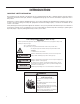
INTRODUCTION IMPORTANT SAFETY INFORMATION The information in this manual is intended for use by a qualified technician who is familiar with the safety procedures required for installation and repair, and who is equipped with the proper tools and test instruments required to service this product.
INTRODUCTION PERSONAL INJURY OR DEATH HAZARDS SAFETY FIRST WARNING Do not remove, disable or bypass this unit’s safety devices. Doing so may cause fire, injuries, or death. ADVERTENCIA Ne pas supprime, désactiver ou contourner cette l´unité des dispositifs de sécurité, faire vous risqueriez de provoquer le feu, les blessures ou la mort. No eliminar, desactivar o pasar por alto los dispositivos de seguridad de la unidad. Si lo hace podría producirse fuego, lesiones o muerte.
INTRODUCTION PERSONAL INJURY OR DEATH HAZARDS 5 • REFRIGERATION SYSTEM REPAIR HAZARDS: • Use approved standard refrigerant recovering procedures and equipment to relieve high pressure before opening system for repair. • Do not allow liquid refrigerant to contact skin. Direct contact with liquid refrigerant can result in minor to moderate injury. • Be extremely careful when using an oxy-acetylene torch. Direct contact with the torch’s flame or hot surfaces can cause serious burns.
INTRODUCTION This service manual is designed to be used in conjunction with the installation and operation manuals provided with each air conditioning system. This service manual was written to assist the professional service technician to quickly and accurately diagnose and repair malfunctions. Installation procedures are not given in this manual. They are given in the Installation/Operation manual which can be aquired on the Friedrich website.
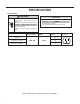
SPECIFICATIONS Model Cooling Heating Volts Cooling Cooling Heating Heating Btu Btu Rated Amps Watts Amps Watts EER CEER Moisture Refrigerant Removal- Refrigerant CFM Charge Sleeve Weight Net./ Pints/HR Ship lbs. FIXED CHASSIS, COOL ONLY (WINDOW INSTALLATION ONLY) CCF05B10A 5250 — 115 3.9 420 — — 12.2 12.1 0.6 R32 8.11 141 44/51 CCF06B10A 6000 — 115 5.0 490 — — 12.2 12.1 0.9 R32 9.52 141 44/51 CCF08B10A 8000 — 115 6.1 640 — — 12.1 12.0 1.
SPECIFICATIONS C B A Model CCF05B10A, CCF06B10A, CCF08B10A CCF10B10A, CCF12B10A Height Inches “B” 13 3/8 Width Inches “A” Depth Inches “C” Minimum Extension Into Room Inches Minimum Extension Outside Inches Window Width Inches Minimum* Maximum 18 5/8 15 5/8 — — 23 36 15 1/8 19 3/4 21 1/2 — — 23 36 13 1/2 18 1/2 19 3/4 — — 26 36 CCW06B10B, CCW08B10AB Figure 203 (Chill Premier Installation) Installation Clearances Improper installation of the Air Condtioner can cause poor
SPECIFICATIONS Electrical Data WARNING ELECTRIC SHOCK HAZARD Turn off electric power before service or installation. All electrical connections and wiring MUST be the National Electrical Code and all local codes which have jurisdiction. NOTICE FIRE HAZARD electically unsafe conditions which could cause moderate or serious property damage. Read, understand and follow the above warning. Failure to do so can result in personal injury or death.
SPECIFICATIONS Electrical Data WARNING Electrical Shock Hazard Make sure your electrical receptacle has the same configuration as your air conditioner’s plug. If different, consult a Licensed Electrician. Do not use plug adapters. Do not use an extension cord. Do not remove ground prong.Always plug into a grounded 3 prong outlet. Failure to follow these instructions can result in death, fire, or electrical shock. Wire Size - Use ONLY wiring size recommended for single outlet branch circuit.
OPERATION Remote Control 1. Power: Turn the air conditioner on and off. This button will clear the TIMER setting. 2. MODE: Press the button to select the mode of operation, AUTO, COOL, DRY, FAN ONLY, HEAT. Note: The HEAT mode is only for some heating models. If you do not need it, press the MODE button for more than 5 seconds to delete the HEAT function, and the COOL mode will be selected automatically.
OPERATION Control Panel USING YOUR AIR CONDITIONER Electronic Control Panel & Remote Control NOTE: This display always shows the room temperature in Fan Mode except when setting the Timer. For Cooling model I TEMP/HR. + :�: :1 :;: ·1 l 0 '? '" MONEY > 2 3 MODE TIM R : 9 8 For Heating model 7 1 6 5 4 I TEMP/HR.
Control Panel OPERATION or HEAT mode and 13
Sequence of Operation OPERATION Main function NOTES: RT------Room Temperature. IPT------Indoor Pipe (Coil) Temperature. ST------indoor Set Temperature. OPT---Outdoor Pipe (Coil) Temperature. CRT---Compensated Room Temperature 1. Cooling mode In the cooling mode, COOL indicator is ON, the set temperature and fan speed could be changed or adjusted. a. When RT-ST≥ 33.8°F the compressor operates if there is not any protection or failure happened. b. When RT-ST< 30.
OPERATION Sequence of Operation temperature drop temperan1Ie 1ise 39.2°F 39.2 ° F high speed wind 35.6 ° F middle speed wind 32 ° F low speed wind 35.6° F Auto fan speed in cooling mode 2. Dry mode While selected to Dry mode, AC works at set temperature to 44.6°F for 3 minutes. After that the set temperature change to be RT 28.4°F, the compressor works as cooling mode, and indoor fan motor operates at low speed.
OPERATION Sequence of Operation 4. Heating mode (for Cooling & Heating pump) When in heating operation mode, the set temperature, fan speed and air direction can be adjusted, compressor does not operate, but electrical heater works, and indoor fan motor starts up 10s later. a ST-RT≥ 33.8°F electrical heater operates b ST-RT < 30.2°F electrical heater stops. c 30.2°F ≤ST-RT < 33.8° electrical heater keeps the original works status . Indoor fan motor control 4.
OPERATION Sequence of Operation a) The indoor fan runs at the set speed when processing sleep mode, after the 1st change, unit runs at low speed, and after the 2nd change, unit runs at low-low speed ( if AC without low-low speed, it runs at low speed instead). 10 hours later AC quits from sleep mode and runs at former set fan speed . b) In SLEEP mode, the vane works according to the preset, after the first change, vane blade works at cold air prevention angle.
OPERATION Sequence of Operation 8.4 The indoor fan motor works as below while RT meets the set temperature to stop compressor: a) The indoor fan motor runs for 1 min according to the set speed continuously, and then stops. b) The indoor fan keeps the stopping status in the following 10 min if RT meets the requirement of compressor stopping work. c) After 10 min, the indoor fan motor runs for 20 seconds and lets the indoor air flow through the evaporator.
Sequence of Operation OPERATION Power off unit: Buzzer buzzing once. Pressing button and\or receiving signal: Buzzer BIBI shortly once. Malfunction: buzzer BIBI shortly 3 times Protection / Failure code 1 Anti-frozen protection for indoor evaporator: If IPT≤32°F for continuous 3min, compressor shut off, fan motor keeps former operation; 3min later, if IPT≥50°F, compressor start up operation and fan motor keeps the former running status.
Refrigeration Sequence Of Operation OPERATION A good understanding of the basic operation of the refrigeration system is essential for the service technician. Without this understanding, accurate troubleshooting of refrigeration system problems will be more difficult and time consuming, if not (in some cases) entirely impossible. The refrigeration system uses four basic principles (laws) in its operation they are as follows: 1. “Heat always flows from a warmer body to a cooler body.” 2.
Hermetic Components Check COMPONENT TESTING WARNING WARNING BURN HAZARD Proper safety procedures must be followed, and proper protective clothing must be worn when working with a torch. CUT/SEVER HAZARD Be careful with the sharp edges and corners. Wear protective clothing and gloves, etc. Failure to follow these procedures could result in moderate or serious injury. Failure to do so could result in serious injury.
COMPONENTS TESTING Fan Motor A single phase permanent split capacitor motor is used to drive the evaporator blower and condenser fan. A self-resetting overload is located inside the motor to protect against high temperature and high amperage conditions. (See Figure 23) WARNING Figure 23 Blower/Fan Motor ELECTRIC SHOCK HAZARD Turn off electric power before service or installation. Extreme care must be used, if it becomes necessary to work on equipment with power applied.
TROUBLESHOOTING Check Thermistors 1. Gain Acces to Main PCB (logic) board 2. Using a multi meter ohm across applicaple pins for the sensor you are checking. 3. All Sensors are 5k. Refer to thermistor chart on following for resistance and temperature deviation. 4. Replace sensor if open or if resistance values deviate by more than 10% of the listed values.
TROUBLESHOOTING Check Thermistors -Resistance Table of Thermistors (5K) 24 Temp Resis Temp Resis Temp Resis Temp Resis Temp Resis -33 130100 7 34252 47 10785 57 8275 97 3119 -32 125518 8 33209 48 10499 58 8063 98 3048 -31 121114 9 32202 49 10221 59 7857 99 2980 -30 116881 10 31228 50 9952 60 7657 100 2913 -29 112811 11 30288 51 9690 61 7462 101 2848 -28 108898 12 29378 52 9437 62 7273 102 2785 -27 105131 13 28499 53 9190 63 7090
TROUBLESHOOTING ROOM AIR CONDITIONER UNIT PERFORMANCE TEST DATA SHEET JOB NAME______________________ TECH’S NAME_________________________ DATE___________ MODEL#_______________ SERIAL #______________________ CHECK THE INSTALLATION ACCEPTABLE NOT ACCEPTABLE YES NO IS A CHASIS GASKET INSTALLED? _____ ____ IS THE FRESH / EXHAUST AIR VENT OPEN? _____ ____ IS A FRIEDRICH SLEEVE INSTALLED? _____ ____ IS A FRIEDRICH OUTDOOR GRILLE INSTALLED? _____ ____ IS MAINTENANCE BEING PERFORMED? ____
Product Does Not Operate At All TROUBLESHOOTING Product does not operate at all. Power supply voltage check Power input voltage on driving load terminal.
TROUBLESHOOTING Indoor Fan Does Not Operate At All Indoor fan does not operate at all.
TROUBLESHOOTING Compressor Or Outdoor Fan Does Not Operate At All Compressor or outdoor fan does not operate at all. Re-input after power of f Set the desired temperature of remote controller to be lower by 2°C or over than room temperature, and start the cooling operation. Does not operate at all. Repeat running/stopping at a short time period. Temperature sensor open/short check Thermistor and evaporator surface contact check.Clearance is needed (5mm).
Display E1 or E2 TROUBLESHOOTING Display E1 and E2 Check the wire connection of indoor temperature sensor assembly.
Models: CCF05A10A CCF06A10A CCF08A10A WIRING DIAGRAMS CCF05B10A, CCF06B10A, CCF08B10A, CCF10A10B, CCF12B10A CCF10A10A CCF12A10A E Figure 801 30
Models: CCW06B10A .
CCW08B10B WIRING DIAGRAMS odels: Models: CCW10B10A.CCW12B10A.
CCW06B10B CCW08B10B PARTS CATALOG FIgure 901 29 30 31 33 5 34 35 6 36 10 23 22 21 13 20 19 18 17 16 15 14 12 9 7 8 11 24 25 26 4 27 3 2 1 33
CCW06B10B CCW08B10B PARTS CATALOG ITEM PART NUMBER PART DESCRIPTION USED ON MODEL 1 68000464 41502-000051 - Base ALL 1 5 68000468 41508-000039 - Cabinet ALL 1 7 68000470 41503-000027 - Propeller Fan ALL 1 8 68000491 22001-000502 - Fan Motor ALL 1 10 68000472 41504-000207 - Vortex Shell ALL 1 12 68000473 42004-000142 - Centrifugal Fan ALL 1 14 68000475 41505-000282 - Electrical Box ALL 1 15 68000009 10303-100042 - Compressor Capacitor CCW06B10B 1 15 68000025 10
PARTS CATALOG FIgure 902 CCF05B10A CCF06B10A CCF08B10A 14 Non-Illustrated Parts 29 Power Cord 30 Remote Control 31 Temp Sensor 49 Installation Kit 16 15 14.3 14.2 14.
PARTS CATALOG CCF05B10A CCF06B10A CCF08B10A ITEM PART NUMBER PART DESCRIPTION USED ON MODEL 1 68000499 Base ALL 1 5 68000012 Cabinet ALL 1 7 68000018 Propeller Fan ALL 1 8 68000011 Fan Motor ALL 1 8 68000494 Fan Motor ALL 1 9 68000053 Back Partition Plate ALL 1 10 68000505 Middle Vortex Shell ALL 1 11 68000503 Up Vortex Shell ALL 1 12 68000473 Centrifugal Fan CCF05B10A 1 12 68000010 Centrifugal Fan CCF06B10A 1 12 68000016 Centrifugal Fan CCF08B10A 1
PARTS CATALOG CCF10B10A CCF12B10A 7 6 8 FIgure 903 10 9 Non-Illustrated Parts 19 Sensor 20 Display PCB 24 Wifi Module 35 Installation Kit 2 2 3 4 5 2.5 1 2.7 1.6 1.8 14 15 16 17 18 37 13 12 11 2.1 2.
CCF10B10A CCF12B10A ITEM PART NUMBER PARTS CATALOG PART DESCRIPTION USED ON MODEL QTY 1 68000160 Front Panel Assembly ALL 1 1.6 68000027 Air Filter ALL 1 2 68000164 Electrical Box Assembly ALL 1 2.1 68000496 Main Pcb ALL 1 2.1 68000035 Power Supply Cord ALL 1 2.5 68000025 Capacitor ALL 1 2.
Friedrich Air Conditioning Company 10001 Reunion Place, Suite 500 San Antonio, TX 78216 800-541-6645 www.friedrich.com ROOM AIR CONDITIONERS LIMITED WARRANTY FIRST YEAR ANY PART: If any part supplied by FRIEDRICH fails because of a defect in workmanship or material within twelve months from date of original purchase, FRIEDRICH will repair the product at no charge, provided room air conditioner is reasonably accessible for service.
THIS PAGE LEFT INTENTIONALLY BLANK.
CUSTOMER SATISFACTION and QUALITY ASSURANCE Friedrich is a conscientious manufacturer, concerned about customer satisfaction, product quality, and controlling warranty costs. As an Authorized Service Provider you play a vital role in these areas. By adhering to the policies and procedures you provide us with vital information on each warranty repair you complete.