
Brochure


INSTALLATION INFORMATION
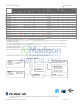
* Minimum extensions when mounted in a window.
** Minimum widths achieved using one side curtain assembly as opposed to both in a standard installation.
† Sleeve P1 does not have In-wall hole dimensions, as these units are xed chassis and should not be installed In-wall.
(B)
(C)
Front
SIDE VIEW
Sleeve Dimensions Drawing
Sleeve
Height
INCHES
Width
INCHES
Depth
with Front
INCHES
Shell Depth
to Louvers
INCHES
Minimum
Extension
Into Room*
INCHES
Minimum
Extension
Outside
*
INCHES
Window Width
INCHES
In-wall Installation
Finished Hole
INCHES
Carton Dimensions
INCHES
Minimum** Maximum Height Width Max. Depth
Height Width Depth
P1† 12"
18
½"
15" 5"
3
½" 10 ¾"
20
1
/8
” 36" NOT FOR THRU-WALL 15
1
/
4
” 22
1
/
4
” 17
1
/
2
”
P6 14” 18
3
/8
” 20
7
/8
” 8
1
/8
”
4
½"
11" 20
1
/8
” 36" 14
1
/8
” 18
7
/8
” 7 ½" 17
7
/8
” 22
3
/
4
” 22”
P7 15" 23
5
/8
"
21
¾” 8 ¾" 4 ½"
12” 25 ¼” 39" 15 ¼" 23
7
/8
” 8" 18
3
/
4
” 26
3
/
4
” 23
7
/
8
”
P8 16
7
/8
” 26" 26
7
/8
” 10
1
/4
"
5
½"
16
5
/8
"
26
½"
42" 17
1
/8
” 26 ¼" 9 " 21
1
/
2
” 29
1
/
2
” 29”
P9 16
7
/8
” 26" 30
3
/8
” 10
1
/4
”
5
½" 19 ½" 26 ½"
42" 17
1
/8
” 26 ¼" 9 “ 21
1
/
2
” 33” 28
7
/
8
”
CIRCUIT RATING/ BREAKER
Model
Circuit Rating
Breaker or
T-D Fuse
Plug Face
(NEMA#)
Power Cord
Length (ft.)
Wall Outlet
Appearance
CP05G10B 125V-15A 5 -15P 6 1/2
CP06G10A, CP08G10A, CP10G10A,
CP12G10A and CP15G10A. EP08G11B.
125V - 15A 5- 5P 6
CP18G30A 250V - 15A 6 - 15P 4 1/2
CP24G30A.
EP12G33B, EP18G33B and EP24G33B.
250V - 20A 6 - 20P 4
3