Service & Parts Manual Dehumidifier Models D25D, D50D, D70D Dehumidifier-2010 Svc Parts (4-2010) Important points on service, and Flow chart for inspecting and repairing the unit ............... 1 Troubleshooting ............................................. 2 Appearance and Control panel ........................ 3 Technical specifications .............................. 4-6 Refrigerator system diagram .......................... 7 Schematic wiring diagram ..............................
IMPORTANT POINTS ON SERVICE OPERATING SAFETY Please follow these instructions carefully : Unplug the unit to avoid any danger from electric shock before disassembling the unit for repair. If there is any sound of the refrigerant circulating when in operation, avoid touching the cooling coils. If you need to perform any welding or soldering, be sure you are in a well ventilated area. Only a qualified professional should perform any welding on the unit.
TROUBLESHOOTING Problem Dehumidifier doesn't work Fan doesn't work Compressor doesn't work Can not dehumidify or the dehumidifcation volume is too low Loud noise and vibration Evaporator is frosted Dehumidification water overflows Possible causes Solution Electricity shutdown or low voltage Wait for electricity to be restored Bad plug or wire is broken Repair or replace Motor is broken Repair or replace Low voltage Call the local electricity company Still under the 3 min protection Wait u
APPEARANCE AIR FILTER CONTROL PANEL OUTLET FOR DEHUMIDIFIED DRY AIR MOIST AIR INTAKE HANDLE CONTINUOUS DRAINAGE HOLE DRAIN BUCKET Electricity cable ROLL CASTORS CONTROL PANEL BUCKET FULL LAMP DEFROST LAMP CURRENT TEMP / TIMER SET DISPLAY Water tank is full,and lamp lights. When low temperature, unit gets into defrosting mode and lamp lights. When machine is running, it displays the current temperature.
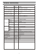
TECHNICAL SPECIFICATIONS ITEM UNIT DEHUMIDIFYING CAPACITY OUTER DIMENSION RATED VOLTAGE RUNNING CURRENT Pint/day 25 (at 80°F , 60%RH) Inches 13.46(W) * 21.46(H) * 9.84(D) V/Hz A COMPRESSOR FAN MOTOR OPERATING CYCLE 115 / 60 4.6 10A 125V 18AWG*3C WIRE SPECIFICATION MODEL INPUT POWER D25D 35D042-A2-ABDA W uF/V 300 35/300 PROTECTOR MR A12228-12095 MODEL LS-16T2-04 INPUT POWER OPERATING CYCLE CAPILLARY W uF/V Inches 47 5/250 0.086(O.D.)*0.047(I.D.)*19.
TECHNICAL SPECIFICATIONS ITEM UNIT DEHUMIDIFYING CAPACITY OUTER DIMENSION RATED VOLTAGE RUNNING CURRENT Pint/day 50 (at 80°F , 60%RH) Inches 14.96(W) * 23.43(H) * 12.01(D) V/Hz A FAN MOTOR 5.9 35D052-A2-ABLL MODEL COMPRESSOR 115 / 60 10A 125V 18AWG*3C WIRE SPECIFICATION OPERATING CYCLE D50D uF/V 40/300 PROTECTOR MR A12274-12095 MODEL LS-16T2-02-N2 INPUT POWER OPERATING CYCLE CAPILLARY W uF/V Inches 47 6/250 0.086(O.D.)*0.047(I.D.)*39.
TECHNICAL SPECIFICATIONS ITEM UNIT DEHUMIDIFYING CAPACITY OUTER DIMENSION RATED VOLTAGE RUNNING CURRENT Pint/day 70 (at 80°F , 60%RH) Inches 14.96(W) * 23.43(H) * 12.01(D) V/Hz A OPERATING CYCLE uF/V PROTECTOR A MODEL FAN MOTOR OPERATING CYCLE CAPILLARY 7.7 41T068-A2-AMLI MODEL INPUT POWER 115 / 60 10A 125V 18AWG*3C WIRE SPECIFICATION COMPRESSOR D70D 40/300 MR A12272-12082 LS-16T2-06 W uF/V Inches 47 6/250 0.086(O.D.)*0.047(I.D.)*31.
REFRIGERATOR SYSTEM DIAGRAM CAPILLARY TUBE DRYER PTC(HEATER) EVAPORATOR CONDENSER COMPRESSOR ASS'Y -7- FAN MOTOR
SCHEMATIC WIRING DIAGRAM D25D SCHEMATIC WIRING DIAGRAM CAPACITOR WHITE O LP YELLOW NO CN 2 N N N CN 4 CN 8 CN 1 CN 2 CONTROL BOARD TRANSFORMER FAN-H P6 P7 F/MOTOR CN 5 COM. FUS E T3.15AL 250V CN 1 BLUE RED FAN-L WHITE COMPRESSOR WHITE BLACK E RED BLUE N L BLACK 115V~60Hz CAPACITOR CN 7 CN 3 MICRO H.sensor T.sensor SWITCH BLUE D6951-870 SCHEMATIC WIRING DIAGRAM D50D, D70D SCHEMATIC WIRING DIAGRAM CAPACITOR WHITE OLP BROWN YELLOW RED FAN-H COM.
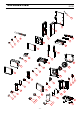
EXPLODED VIEW D25D 33 40 42 37 41 46 27 45 51 44 38 43 39 36 48 35 49 21 34 47 20 30 19 29 50 28 18 32 9 31 10 17 8 26 16 15 25 7 24 6 14 23 12 22 5 1 11 13 3 4 -9- 2
D25D Ser vice Par ts List Ref # 1 2 3 4 7 8 9 10 11 12 13 14 15 16 17 18 19 20 21 22 23 24 25 26 27 28 29 31 32 33 34 35 36 37 38 39 40 41 42 43 44 45 46 47 48 49 50 51 Friedrich Par t # 679-041-52 679-042-07 679-041-24 679-041-65 679-041-68 679-041-00 679-041-76 679-042-08 679-041-11 679-041-08 679-041-05 679-041-29 679-041-32 679-041-28 679-041-85 679-041-54 679-041-21 679-041-57 679-041-55 679-041-13 679-041-84 679-041-81 679-041-77 679-041-15 679-041-16 679-041-19 679-041-17 679-041-20 679-041-82 679-0
EXPLODED VIEW D50D, D70D 53 63 27 54 62 26 41 25 24 47 23 16 46 42 44 51 52 43 45 61 35 60 36 14 37 49 17 48 15 34 31 13 30 39 20 19 40 18 32 38 57 12 58 33 10 11 59 6 8 9 5 28 29 55 3 21 56 22 4 50 1 7 2 - 11 -
D50D & D70D Ser vice Par ts List Ref # 1 2 3 4 7 8 9 10 11 12 13 14 15 16 17 18 19 20 21 22 23 24 25 26 27 28 29 30 31 32 33 34 35 36 37 38 39 40 41 42 43 44 45 46 47 48 49 50 51 52 53 54 55 56 57 58 59 60 62 63 Friedrich Par t # D70D D50D 679-041-53 679-042-07 679-041-25 679-041-67 679-041-69 679-041-00 679-041-76 679-041-12 679-041-06 679-041-09 679-041-78 679-041-82 679-041-15 679-041-16 679-041-20 679-041-19 679-041-18 679-041-75 679-041-01 679-041-66 679-041-04 679-041-03 679-041-07 679-041-00 679-041
Friedrich Air Conditioning Company P.O. Box 1540 San Antonio, TX 78295 210.357.4400 www.fnedrich.com DEHUMIDIFIERS LIMITED WARRANTY FIRST YEAR ANY PART: If any part supplied by FRIEDRICH fails because of a defect in workmanship or material within twelve months from date of original purchase, FRIEDRICH will repair the product at no charge, provided the provided the product is transported to a Friedrich Authorized Service Center for reoair. ALL transportation charges are the sole responsibility of the owner.