Contents Caution Statements Composition of the Al-Condltioner . Before Operation Spacial Remarks Troubleshooting . Installation and Maintenance 1. Safety Notice... 2. The Tools and Instruments for Installation 3. The Installation of the Indoor Unit 3.1 The Initial Check 3.2 Installation 4. Refrigerant Pipe .. 4.1 The Pl pa Material 4.2 The Connection of the Pipe . 5. Drain Piping 6. Electrical wiring 6.1 General check. 6.2 Change of Static Pressure 6.3 Electrical Installation .
Cautions Alert Symbols: PQS: The symbol refers to a hazard which can result in severe personal injury or death. A WARNING: The symbol refers to a hazard or an unsafe practice which may result in severe personal injury or death. A\ CAUTION |: The symbol refers to a hazard or an unsafe practice which may result in personal injury, product or property damage. NOTE: It refers to the remarks and Instruction to the operation, maintenance, and service.
CAUTION Statements AA WARNING NOTE: @ Storage condition: ® Never use gasoline or other inflammable gas near the air-conditioner, which is very: ‘dangerous: ® When the air conditioner. operation is abnormal; such as: bunt smell; deformation, fire, ‘smoke, and forbidden to continue using the air conditioner, the main: power. ‘switch of the air conditioner must be: cut off immediately and the agent must be: contacted. Do not turn the air-conditioner on and off from the main power switch.
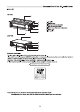
Composition of the Al r-condlitioner Indoor unit 9K~18K 1. Air inlet 2. Electric box 3. Refrigerant pipe (Liquid) 4. Refrigerant pipe (Gas) 5. Drain pipe (Connect with pump) 6. Drain pipe 7. Air outlet 24K~36K were N Remote controller You can control the ale-conditioner with the wire remote controller. It is used for controlling power ON/OFF, setting the running mode, temperature, fan speed and other functions. There are different types of remote controllers that can be used.
Before Operation Remarks ® 3 minutes protection after compressor stop To protect compressor, it will be continue to be off for at least 3 minutes once it has stopped. @ § minutes protection Compressor must run for at least 5 minutes once operational. In the 5 minutes, compressor will not stop even the room temperature reaches the setting temperature point unless you use remote controller to tum off the unit {all indoor unit can be muted off by user).
fore Operation 5. Mode Interfere (Only for mull-split, 9K~24K) For the reason that all indoor units use one outdoor unit, cutthroat unit can only run with same mode {cooling or heating), so, when the mode you set Is different from the mode that outdoor Is running with, mode Interfere occurs. Following shows the mods interfere sens. Cooling Dry Heating Fan Cooling normal Dry mode interfere Heating Fan Outdoor unit always run with the mods of first indoor unit that muted on.
Installation and Maintenance 2. The Tools and Instruments for Installation Number Tool Number Tool 1 Standard screwdriver 8 Knife or wire stripper 2 Vacuum pump 9 Level 3 Charge hose 10 Hammer 4 Pipe bender 1 Power drill 5 Adjustable wrench 12 Tube expanded 6 Pipe cutter 13 7 Phillips screwdriver 14 Measuring tape 3. The Installation of the Indoor Unit During installation, do not damage the insulation material on the surface of the indoor unit. 3.
+ Optimum air distribution is ensured. + The air passage is not blocked. + Condensate can drain properly. + The ceiling is strong enough to bear the weight of the indoor unit. + False ceiling does not seem incline. Sufficient clearances for maintenance and servicing is ensured (See Fig.3.1.
3.2.3 Install the Indoor unit. The installation of the indoor unit is shown in Fig. 3.4. Suspension bolts (4-M10 or W3/8) ( Field supplied ) M10 or WI 8) (Flied supplied) Fig. 3.4 The installation of the indoor unit {1) How to fix the suspension bolts and the nuts As shown in the figures 3.5, the nuts are fixed four bolts. _ Nut Indoor unit Washer Double fut Fig. 3.
4. Refrigerant Pipe Use the refrigerant according to outdoor nameplate. ‘When carrying on the leakage check and test, do not mix in the oxygen, the acetylene and flammable and the virulent gas, for these gases are quite dangerous, and may possibly cause explosion. It is suggested that the nitrogen be used to perform these experiments. 4.1 The Pipe Material {1} Prepare the copper pipe on the spot. (2) Choose dustiness, non-humid, clean copper pipe.
Installation and Maintenance §. Drain piping « Drain piping passing indoors Install the drain piping * Drain sockets. * Make sure the drain works properly . * Referring the figure below, insulate the drain socket * Prepare polyvinyl chloride pipe with a 1.3 and drain hose using the Included large sealing pad. outer diameter. * The diameter of drain pipe connection hole should be same as that of the drain pipe.
Installation and Maintenance 6. Electrical Wiring 6.1 General Check * When clamping the wiring, use the included clamping material to prevent external pressure being exerted on the wiring connections and clamp firmly. « While performing wiring work, make sure the wiring is proper and does not cause the control box lid to stick up, then close the cover firmly. When attaching the control lid, make sure you de not pinch any wires.
Installation and Maintenance 6.2 Change of Static Pressure The static pressure can be freely adjusted by using specific wire remote controller. . Model | The Range LCD 7 Error Indicator | (capacity | oof Function Code Sat oa Parameter Code | Buh) | osc — 0-50 function code value equals 0.020 In HO static pressure values, SKIBOB (5 50Pa) | mots than 50 Is 0.20 In. H,0 (50Pa), | Function Code default: 0 (0.18 in.
Installation and Maintenance 6.3 Electrical Installation * Use an ELB (Electric Leakage Breaker). If not used, it will cause an electric shock or a fire. * Da not operate the system until all the check points have been cleared. (A) Check to ensure that the insulation resistance is more than 2MQ, by measuring the resistance between ground and the terminal of the electrical parts. If not, do not operate the system until the electrical leakage is found and repaired.
Alerta Embolso: Indicaciones de advertencia 9 : Este símbolo indica un riesgo que puede resultar en lesiones personales graves o muerte. : Este símbolo Indica un Nesgo o una practica Insegura que podría resultar en lesiones personales graves o muerte. : Este símbolo indica un riesgo o una practica insegura que podría resultar en lesiones personales o dacios a la propiedad o el producto. NOTA. : Indica la existencia de comentarios e instrucciones acerca del funcionamiento, el mantenimiento y el servicio.
Compostelano del arle acondicionado Unidad Interior 9K~18K 1. Entrada de aire 2. Caja eléctrica 3. Tubería de refrigerante (Liquido} 4. Tubería de refrigerantes (Gas) 5. Tubería de drenaje (Conectar con la bomba) 6. Tubería de drenaje 7. Sallad de arle 24K~36K © ara N Mando a distancia Puede controlar el aire acondicionado con un mando a distancia con cable. Se utiliza para controlar el ENCENDIDO APAGADO [ON/OFF] , ajustar el modo de funcionamiento, la velocidad del ventilador y foras funciones.
Antes de Operar Comentarios especiales ® 3 minutos de protección después de la parada del compresor Para proteger el compresor, segudar apagado durante al menos 3 minutos una vez se haya detenido. ® 5 minutos de protección El compresor debe funcionar durante al menos 5 minutes una vez en funcionamiento.
Instalación y mantenimiento + La instalación debe ser realizada por personal cualificado. (Una instalación inadecuada podría causar fugas de agua, descargas eléctricas o incendios). + Instale la unidad en conformidad con las Instrucciones Incluidas en este manual (Una Instalación Incompleta podría causar fugas de agua, descargas eléctricas o incendios).
Distribución optima del aire garantizada. + El paso de aire no esta bloqueado. + El condensado puede drenar apropiadamente. + El techo es lo bastante fuerte para soportar el peso de la unidad interior. + El tocho falso no parece estar en una pendiente. + Se dispone de espacio libre suficiente para el mantenimiento y la reparación {véase la Fig.
3.2.3 Instalar la unidad interior La instalación de la unidad interior se muestra en la Fig. 3.4. Pomos de suspensión (4-M10 0 W3/B) (Incluyes) Tuercas y ‘arandelas (4-Me 00 Wa) (incluidas) Fig. 3.4 Instalación de la unidad interior {1) Como fijar los peamos de suspensión y las tuercas Como se muestra en las figuras 3.5, las tuercas son cuatro peamos fijos. fae Unidad Interior racimad unte Sas om Arandelas Tuerca doble’ Fig. 3.
4. Tubería de refrigerante Utilice el refrigerante siguen las indicaciones del exterior Al llevar a cabo el control y la prueba de fugas, no mezcle el oxigeno, el acetileno, el gas inflamable y el gas virulento, ya que estos gases son bastante peligrosos y pueden provocar una explosión. Se sugiera que se utilice el nitrógeno para realizar estos experimentos. 4.1 Material de la tubería {1} Prepare la tubería de cobre al momento. (2) Elija una tubería de cobre limpia, sin polvo ni humedad.
5. Tubería de drenaje Instale las tuberías de drenaje + Asegúrese de que el drenaje funcione correctamente. « Prepare un tubo de cloruro de polinomio con un espesor de 1,3 pulga. (32 mm) de diámetro exterior. + El diámetro del orificio de conexión con la tubería de drenaje debe ser igual que el de la tubería de drenaje. + Acorte la tubería de drenaje y manténgala inclinada con una pendiente del 1% para evitar que se formen bolsas de aire.
Instalación y mantenimiento 6. Cableado eléctrico 6.1 Revisable general + Al sujetar el cableado, utilice el material de fijación incluido para evitar gue se ejerza presión extrema sobre las conexiones de cableado y sujete firmemente. « Al realizar los trabajos de cableado, aseglares de que el cableado sea correcta y no provoque que la cubierta de |a caja de control se atasque y, a continuación, cierre la cubierta con firmeza. Cuando coloque la cubierta de control, asegúrese de no pinzar ningún cable.
Instalación y mantenimiento + Utilice un disyuntor de fugas eléctricas. Si no lo utiliza, podría causar descargas eléctricas o incendios. « No opere el sistema hasta que haya comprobado todos los puntos de verificación. (A) Asegúrese de que la resistencia del alistamiento sea superior a 2MQ midiendo la resistencia entre tierra y la terminal de las piezas eléctricas. Si no, no utilice el sistema hasta encontrar y reparar la fuga eléctrica.
Contenus Consignes de précaution .. Composition du climatise 1 Avant la mise en marche Remarques spéciales Dépannage . Installation et entretien 1. Avis de 2. Outils et Instruments d'Installation . 3. L'installation de ['unité intérieure 3.1 La vérification initiale. 3.2 Installation... 4. Tuyau du réfrigérant.. 4.1 Le matériel du tuyau .. 4.2 La connexion du thuya 5. Tuyauterie de vidange... 6. Câblage 8.1 Vérifications générale: 6.2 Changement de la pression statique . 6.3 Installations électriques... 7.
Consignes de précaution Symboles d'alerte PINE VIE SH : Le symbole fait référence a un danger pouvant entrain des blessures graves ou la mort. : Le symbole fait référence & un danger ou & une pratique dangereuse qui pourrait entraîner des blessures graves ou la mort. : Le symbole fait référence & un danger ou & une pratique dangereuse pouvant entraîner des blessures, des dégâts matériels du produit ou d'une propriété.
Consignes de précaution AN ATTENTION ® Ne jamais utiliser d’essence ou d’antistress gaz inflammables pré du climatiseur. Clos frais dangereux. ® Lorsque le fonctionnement du climatiseur présente des anomalies, telles que Ja présence d'odeur de bels, de déformation, de feu, de fumes, ef ainsi de site, i ast mordit de continuer a utiliser 1s climatiseur, la commutateur d'alimentation.
Composition du climatiseur Unité Intérieure 9K~18K 1. Entrée d'air 2. Boîtier électrique 3. Tuyau réfrigérant (liquide) 4. Tuyau réfrigérant (gaz) 5. Tuyau de drain {se connecte a la pompe} 6. Tuyau de vidange 7. Sortie d'air won N Télécommande Vous pouvez contrôler le climatiseur en utilisant soit la télécommande a fil. C'est utilisé pour contrôler I'alimentation ON/OFF, régler le mode de fonctionnement, la température, la vitesse du ventilateur et d'autres fonctions.
Avant la mise en marche Remarques spéciales « Protection de 3 minutes après Aménité du compresseur Pour protéger le compresseur, il continuera d’être éteint pendant au moins 3 minutes, une fois qu'il est arrête. * Protection de 5 minutes Le compresseur doit fonctionner pendant au moins 5 minutes une fois opérationnel.
Avant la mise en marche 5. Mode interférence (uniquement pour multi Split) Étant donné que toutes les unités intérieures utilisent une unité extérieure, une unité extérieure peut uniquement fonctionner avec le mémé mode (refroidissement ou chauffage), par conséquent, le mode que vous paramétrez ast différent du mode avec lequel I'unité extérieurs fonctionne et une interférence de mode se produit.
Installation et entretien A wis EN Gare » Ni installez pas le climatiseur a un endroit oli danger d'exposition a une fuite de gaz inflammable (sl le gaz fut dans le bâtiment st s'accumule autour de l'unité, un Incendie peut se déclencher.) « Installez la tuyauterie d'évacuation conformément aux instructions de ce manuel. (Une tuyauterie Inadéquate peut causer une Inondation). « Semez 'écrou évasé conformément aux spécifications avec une clé dynamométrique.
* Une répartition optimale de L’air ast assurée. © Lo passage a air n'est pas blocs. © Lo condensat peut se drainer correctement. » Le plafond est assez résistant pour supporter le poids de ['unité intérieurs. « Un sous plafond ne semble pas être incliné. « Un espace suffisant pour la maintenance et I'entretien est garanti.
3.2.3 Installation de I'unité intérieure. L'Installation de I'unité Intérieurs est illustrée sur la Fig. 3.4. Boulons de suspension (4-M10 ou W/8) {roumi sur dits) Fig. 3.4 L'installation de ['unité intérieure {1)Comment attacher les boulons de suspension et les écrous comme illustrés sur les figures 3.5, les écrous sont fixés avec 4 boulons. intercourses Fig. 3.
4. Tuyau du réfrigérant Utilisez le réfrigérant selon les Informations fournies sur la plaque signalétique extérieure. Lorsque vous effectuez la vérification et le test de fuite, ne mélangez pas l’oxygéné, 'acétylène et des gaz violents et inflammables, car ces gaz sont relativement dangers, et peuvent provoquer des explosions. Il est suggéré d'utiliser du nitrogène pour effectuer ces expérimentations. 4.1 Le matériel du tuyau {1)Préparez le tuyau de cuivre sur place.
5. Tuyauterle de vidange Installation de la tuyauterie de vidange * Rassurez-vous que le drain fonctionne correctement. « Préparez un tuyau en chlorure de polyvinyle diamètre extérieur. » Le diamètre du trou de raccordement du tuyau de drainage doit &tre identique a celui du tuyau de drainage. = Gardez le tuyau de vidange court et incliné vers le bas & une pente d'au moins 1/100 pour éviter la formation de poches d'air.
6.2 Changement de la pression statique La pression statique peut &tre ajustée facilement a l'aide d'une télécommande filaire spécifique. LCD Fig 6.2 Réglage de la pression statique : tourd Modale |La gamme de Indicaleurdemeut | (Rapacité | pression Jeu de code de fonction Cotsdopuamite | en Blu) | _statique 0.020 po.
Installation et entretien 6.3 Installations électriques « Utilisez un ELB (disjoncteur de fuite électrique). Si non utilisé, cela provoquerait un choc électrique ou un Incendie. © Ne faites pas fonctionner le système avant que tous les points de vérification aient été complétés. (A) Vérifiez que la résistance d'isolement est supérieurs mesurant la résistance entre la masse et la borne des pisses électriques.