Vert-I-Pak® Single Package Vertical Air Conditioning System A-Series 24,000 BTU/h Installation & Operation Manual 920-159-01 (10-03)
920-159-01 (10-03) Table of Contents Installation Recommendations......................................................................................................................................................... 3 I. General Specifications Model Number Identification Guide ................................................................................................................................... 4 VERT-I-PAK Chassis Specifications ..............................................................
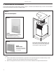
920-159-01 (10-03) Vert-I-Pak Installation Recommendations 6" 60" RECESS OK For proper unit performance and maximum operating life please refer to theSMALL minimum installation clearances below. Figure 1 60" 60" 60" VERT-I-PAK® units must be installed on an outside wall. 60" Confined spaces and/or covered areas should be avoided. Units should be installed no closer than 12" apart when two units are side by side.
920-159-01 (10-03) Section I. General Specifications VERT-I-PAK® MODEL IDENTIFICATION GUIDE MODEL NUMBER V E ENGINEERING CODE SERIES V=Vertical Series E=Cooling with or without electric heat H=Heat Pump OPTIONS RT = Standard Remote Operation SP = Seacoast Protected ELECTRIC HEATER SIZE A-Series 00 = No electric heat 25 = 2.5 KW 34 = 3.4 KW 50 = 5.0 KW 75 = 7.
920-159-01 (10-03) II. Installation 1) Utility Closet Dimensions Recommended utility closet dimensions and a typical indoor installation are illustrated in Figure 1. Three inches minimum clearance on three sides of the unit must be allowed for return airflow, installation access and service access. See Figures 1 & 2 for clearances and reference dimensions.
920-159-01 (10-03) 2) Wall Plenum and Architectural Louver Installation A. Install the wall plenum (VPAWP1-8/1-14) components in accordance with the installation instructions provided with each accessory. IMPORTANT REMINDER: FRIEDRICH WALL PLENUM IS NOT DESIGNED TO CARRY STRUCTURAL LOADS. PROPER WALL HEADER CONSTRUCTION IS REQUIRED. THE PLENUM REQUIRES PROPER FLASHING, SHIM AND CAULK FOR A WEATHER RESISTANT INSTALLATION. B.
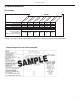
920-159-01 (10-03) 3) Electrical Information Electrical Data Voltage ( V) LRA - Comp. (A) Cooling Current (A) MIN. Ckt. Amps (A) Max Branch Circuit Fust (Amps) Power Connection Recommended Branch Circuit Wire Sizes* AWG - American Wire Gauge 230/208 68 13.7/12.4 17.2/15.9 25/25 14/14 00 10 K /V EA A VH /V EA A VH 24 24 K 24 VH A /V EA /V EA A VH K 75 50 K 24 24 /V EA A VH VH A /V EA 24 K K 25 34 MODEL 230/208 230/208 230/208 230/208 230/208 68 68 68 68 68 13.7/12.4 13.7/12.4 13.
920-159-01 (10-03) IMPORTANT: ALL 208/230V CHASSIS MUST BE HARD WIRED WITH PROPERLY SIZED BREAKER. SEE NAMEPLATE FOR SPECIFIC CHASSIS ELECTRICAL REQUIREMENTS. SEE PAGE 9 - FIGURE 8 FOR UNIT WIRING AND WALL THERMOSTAT WIRING. SEE PAGE 7 FOR WIRE SIZE. USE HACR TYPE BREAKERS TO AVOID NUISANCE TRIPS. ALL FIELD WIRING MUST BE DONE IN ACCORDANCE WITH NEC AND LOCAL CODES. 3) Electrical Information (continued) Figure 6 Electrical Requirements Note: All field wiring must comply with NEC and local codes.
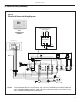
20-159-01 (10-03) 3) Electrical Data (continued) Figure 8 Electrical & Thermostat Wiring Diagrams FOR 208 VOLT MODELS ONLY MOVE THE WHITE WIRE AS SHOWN BELOW WHITE BLACK RT2 THERMOSTAT (FRONT) COM. 208V 240V TRANSFORMER THERMOSTAT CONNECTIONS (EAR) 24V UP G R R W B Y C RED BLACK WHITE RED HEATER 2.5 KW & 3.4 KW 5 KW YELLOW BROWN HEATER 7.
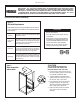
920-159-01 (10-03) 4) Indoor Return Air Grille Installation There are three Indoor Return Air Grille options as shown in Figure 9. Choose the option that best suits your needs. Use the installation instructions provided with accessories for installation details. Figure 9 Return Air Grille Options Option 1 VPRG4 Return Air Grille with Access Panel A field-supplied (25" x 20") filter is mounted inside the hinged access door.
920-159-01 (10-03) 5) Indoor Airflow Data 6) Chassis Installation The Vert-I-Pak A series units must be installed with a free return air configuration. The table below lists the indoor airflow at corresponding static pressures. All units are shipped from the factory and are rated at low speed. NOTE: Prior to installing the chassis, ensure that the drain pan and line are free from debris. To change to high speed replace the low speed lead (blue) with the high speed lead (black) on the blower relay. .
920-159-01 (10-03) 7) Chassis Final Connections With the chassis in place, you are now ready to begin chassis connections: A. Move the thermostat switches to "OFF" and "AUTO." This will keep the thermostat from cycling the chassis until final connections are complete. B. Connect the ductwork onto the 10" collar. Plastic wireties (field supplied) are suggested to secure the ductwork in place. Use 2 wire ties, one for each inner and outer flex duct sleeve. RT2 Digital Thermostat D.
920-159-01 (10-03) 12) Fresh Air Door 15) Routine Maintenance The Fresh Air Door is an "intake" system. The fresh air door is opened via a slide on the front of the chassis located just above the indoor coil. Move the slide left to open and right to close the fresh air door. The system is capable of up to 60 CFM of fresh air @ ~.3" H20 internal static pressure.
920-159-01 (10-03) FRIEDRICH AIR CONDITIONING CO. Post Office Box 1540 · San Antonio, Texas 78295-1540 (210) 357-4400 · FAX (210) 357-4480 VERT- I-PAK® A SERIES SINGLE PACKAGE VERTICAL AIR CONDITIONERS LIMITED WARRANTY SAVE THIS CERTIFICATE. It gives you specific rights, you may also have other rights which may vary from state to state and province to province. In the event that your unit needs servicing, contact your nearest authorized service center.
920-159-01 (10-03) IV. Vert-I-Pak Accessories MODEL DESCRIPTION VPAWP1-8 WALL PLENUM Two-part sleeve that telescopes in and out from 5 1/2" to 8" in depth. The wall plenum sits inside the exterior wall penetration. DIMENSIONS: 30 3/8" high x 24 1/8" wide. CUTOUT DIMENSIONS: 30 7/8" high x 24 5/8" wide. VPAWP1-14 Same as VPAWP1-8, but telescopes 8" to 14" as required. VPAL2 ARCHITECTURAL LOUVER Extruded aluminum louver that attaches to the outdoor section of the wall plenum.
Use Factory Certified Parts. FRIEDRICH AIR CONDITIONING CO. Post Office Box 1540 · San Antonio, Texas 78295-1540 4200 N. Pan Am Expressway · San Antonio, Texas 78218-5212 (210) 357-4400 · Fax (210) 357-4480 www.friedrich.com Printed in the U.S.A.