
Installation & Operation Manual


36 37
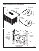
Figure 68
FRR024
B
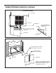
Figure 69
FRR053
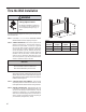
LOCATION OF GRILLE
REMOVAL TOOL
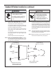
OPTIONAL: The factory assembles the supply cord so that it exits the left
side of the unit at the bottom. At the consumer’s discretion, pull
the supply cord taut through the loops (refer to Cord Routing
Change, Figure 70) and route the cord down.
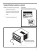
STEP 14. To attach and prevent damage to the front grille, align the cord
notch over the cord and center the fresh air lever, then align
and tighten the four (4) captive screws as indicated by the
arrows in Figure 69. Before closing the front panel, be sure
the lter is in place. Make sure curtains do not block the side
air intakes.
STEP 15. Refer to the Control Panel Operation section for instructions.
You are now to control the comfort level of the room.
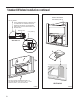
Use Tool Provided
Please use the provided tool to attach the decorative front to the chassis.
USE HAND TOOLS
DO NOT
OVERTIGHTEN
Standard Window Installation continued
POWER CORD CLIP
CHASSIS SEAL GASKET (ITEM 13)
NOTE: WHEN INSTALLING THE CHASSIS
SEAL GASKET, BEGIN AT EITHER BOTTOM
CORNER AND GO UP THE SIDE & ACROSS
THE TOP & DOWN THE OPPOSITE SIDE.