
Service & Parts Manual (Non Q) (2019, 2020, 2021, 2022)
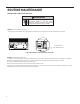
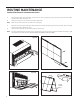
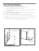

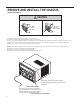
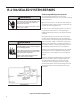
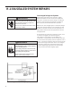
Table Of Contents
- INTRODUCTION
- SPECIFICATIONS
- OPERATION
- ROUTINE MAINTENANCE
- REMOVE AND INSTALL THE CHASSIS
- R-410A SEALED SYSTEM REPAIR
- COMPONENT TESTING
- Hermetic Components Check
- Reversing Valve Description And Operation
- Testing The Reversing Valve Solenoid Coil
- Checking The Reversing Valve
- Replace The Reversing Valve
- Touch Test Chart : To Service Reversing Valves
- Compressor Checks
- Compressor Replacement
- Fan Motor
- Capacitors
- Heating Element
- Drain Pan Valve
- Testing the User Interface and Electronic Control Board
- Thermistors Description
- Electronic Control Board Identification
- Replace the Electronic Control Board
- Replace the User Interface
- TROUBLESHOOTING
- WIRING DIAGRAMS
- PARTS CATALOG
- Available Accessories

41 PB
ROUTINE MAINTENANCE
Remove And Install The Front Cover
WARNING
ELECTRIC SHOCK HAZARD
Disconnect power to the unit before
servicing. Failure to follow this warning
could result in serious injury or death.
Remove the decorative front cover.
1. Using the tool provided (see gure below), loosen the four (4) captive screws as shown in gure 401
B
Location of the
Grill Removal Tool
Install the decorative front cover.
1. Tighten the four (4) captive screws as indicated by the arrows in the gure above before closing the front panel
(do not over tighten). Ensure the lter is in place. Make sure curtains do not block the side air intake
2. Notes on reattaching the decorative front cover:
Align the cord notch over the cord and center the fresh air lever.
Align the cover over the User Interface (UI) to ensure it is clear around it and it does not depress any buttons. If not
installed correctly the wrench alert symbol could ash.
Figure 401 (Remove and Install the Front Cover)