
2014 960-914-06 (General SVC)


- 49 -
Only for training and service purposes
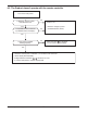
6.6 Troubleshooting Indoor Error
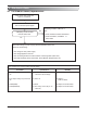
Check Point
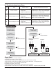
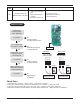
1. Unplug the sensor on Indoor unit PCB.
2. Estimate the resistance of each sensor.
3. If the resistance of the sensor is 10KΩ/ 5KΩ at 25°C, then sensor is normal.
4. If the resistance of the sensor is 0 KΩ or ∞, then sensor is abnormal. ’ Change the sensor.
5. Plug the sensor on Indoor unit PCB and Power ON.
6. Estimate the voltage of each sensor.
7. If the voltage of the sensor is 2.5Vdc at 25°C, then sensor is normal.
8. If the resistance of the sensor is 0 or 5Vdc, then sensor is abnormal. ’ Repair or Change the PCB.
10k
Unplugged Plugged
Check the resistance
Check the voltage
V
2.5Vdc
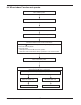
Unplug the sensor
on Indoor unit PCB
Estimate the Voltage
of each sensor.
Is the voltage of
the sensor 2.5Vdc
at 25˚C
Repair or Change the PCB.
Check the
Connector connection
Is it normal ?
Estimate the resistance
of each sensor.
Plug the sensor
on Indoor unit PCB
Is the resistance of
the sensor 10 /
5k at 25˚C?
Yes
Yes
No
Correct connection
Yes
No
Correct connection
No
Correct connection
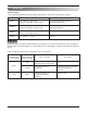
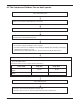
Check Flow Chart
01
02
06
Indoor air sensor
Indoor inlet pipe sensor
Indoor outlet pipe sensor
•
Connector connection error
• Faulty PCB
•
Faulty sensor (Open / Short)
•
Connector connection error
• Faulty PCB
•
Faulty sensor (Open / Short)
•
Connector connection error
• Faulty PCB
•
Faulty sensor (Open / Short)
Normal resistor : 10KΩ/ at 25˚C (Unplugged)
Normal voltage : 2.5Vdc / at 25˚C(Plugged)
Refer to sensor resistance table.
Normal resistor : 5KΩ/ at 25˚C(Unplugged)
Normal voltage : 2.5Vdc / at 25˚C(Plugged)
Refer to sensor resistance table.
Normal resistor : 5KΩ/ at 25˚C(Unplugged)
Normal voltage : 2.5Vdc / at 25˚C(Plugged)
Refer to sensor resistance table.
Display
code
Title Cause of error Check point & Normal condition