
2014 960-914-06 (General SVC)


- 54 -
Only for training and service purposes
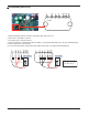
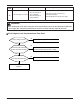
Is the connection of
GND,GND1,GND2,
correctly connected?
Change PCB
❊ CH05 is displayed at indoor unit,
CH53 is displayed at outdoor unit.
Check the input power
AC230V (Outdoor,
Indoor unit)
Is it normal ?
(230V±10%)
Check the communication
wires are correctly
connected.
Is it normal ?
Yes
Yes
No
Needs electric work
Yes
No
Correct connection
No
Adjust the connection
of wire Confirm the
wire of "Live",
"Neutral", "Signal"
1(L1)
2(L2)
1(L1)
2(L2)
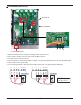
Check the resistance
between communication
line and GND.
(Normal : Over 2M)
Is connector for
communication
correctly connected?
Is it normal ?
Yes
No
Correct connection
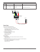
Check Flow Chart
05
/
53
Communication
(Indoor÷Outdoor)
• The connector for trans-
mission is disconnected.
• The connecting wires
are misconnected.
• The communication line
is break
• Outdoor PCB is
abnormal.
• Indoor PCB is abnormal.
• Synchro # of IDU is
abnormal.
• Check power input AC 230V. (Outdoor, Indoor)
• Check connector for transmission
• Check wires are misconnecting.
• Check transmission circuit of outdoor PCB
• Check transmission circuit of indoor PCB
• Check # of IDU setting DIP SW
Display
code
Title Cause of error Check point & Normal condition