
Multi Zone Service Manual - General


5. Trouble Shooting
- 70 -
Only for training and service purposes
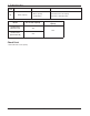
Check Point
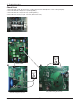
1. Check the CN_(L),CN_(N) Connection condition at the Inverter PCB.(Refer to outdoor wiring diagram)
2. Check the DC Link voltage at not operating(280V
↑
)
3. Check the DC Link voltage at Comp operating(340V
↑
)
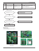
4. Check DC Link Sensing Signal : 2.4~2.8V (Refer the Picture)
Vdc
< Main PCB>
<DC Link Voltage Check Point>
<DC_LINK Sensing Check P
oint>
< Input Power Source Check Point >
Vdc