Single Zone Air Conditioner SVC MANUAL(General) CAUTION Before Servicing the unit, read the safety precautions in General SVC manual. Only for authorized service personnel.
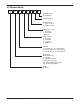
Air Conditioner Service Manual TABLE OF CONTENTS Part 1 General Information ..........................................................................................................3 1. Safety Precautions........................................................................................................4 2. Model Line Up................................................................................................................7 3. Nomenclature ......................................................
Part 1 General Information 1. Safety Precautions ............................................................................................................4 2. Model Line Up .....................................................................................................................7 3. Nomenclature......................................................................................................................
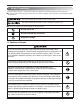
1. Safety Precautions To prevent injury to the user or other people and property damage, the following instructions must be followed. n Incorrect operation due to ignoring instruction will cause harm or damage. The seriousness is classified by the following indications. This symbol indicates the possibility of death or serious injury. This symbol indicates the possibility of injury or damage to properties only. n Meanings of symbols used in this manual are as shown below. Be sure not to do.
Do not use a defective or underrated circuit breaker. Use the correctly rated breaker and fuse. Otherwise there is a risk of fire or electric shock. Install the panel and the cover of control box securely. Otherwise there is risk of fire or electric shock due to dust, water etc. Indoor/outdoor wiring connections must be secured tightly and the cable should be routed properly so that there is no force pulling the cable from the connection terminals.
1.2 Inspections after Repair Check to see if the power cable is not dirty or loose. If the plug is dusty or loose it can cause an electrical shock or fire. Do not use a spliced power cable or extension cable, or share the same power outlet with other electrical appliances. otherwise, it can cause an electrical shock, excessive heat generation or fire. Do not insert hands or other objects through the air inlet or outlet while the product is operating.
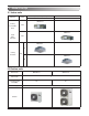
2. Model Line Up 2.1 Indoor units Category Chassis Name Capacity Index[kBtu/h] 24 36 MD24Y3J Ceiling Concealed Duct BG MD36Y3J High Static Pressure BR MC24Y3J TP Ceiling Cassette 4way MC36Y3J TM 2.2 Outdoor units DC Inverter MR24UY3J MR36UY3J No.
3.
2.
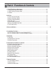
Part 2 Functions & Controls 1. List of Functions & Accessory ......................................................................................11 1. Ceiling Concealed Duct Indoor......................................................................................11 2. 4-Way Ceiling Cassette Indoor .....................................................................................12 3. Outdoor .............................................................................................................
1. List of Functions & Accessory 1. Ceiling Concealed Duct Indoor Category Functions Remark Air supply outlet Airflow direction control (left & right) Airflow direction control (up & down) Auto swing (left & right) Air flow Auto swing (up & down) Airflow steps (fan/cool/heat) Chaos wind(auto wind) Jet cool/heat Swirl wind Triple filter (Deodorizing) Plasma air purifier Air purifying Allergy Safe filter Long-life prefilter (washable / anti-fungus) Drain pump E.S.P.
2. 4-Way Ceiling Cassette Indoor Category Air flow Air purifying Installation Reliability Convenience Individual control Function Remark Air supply outlet Airflow direction control(left & right) Airflow direction control(up & down) Auto swing(left & right) Auto swing(up & down) Airflow steps(fan/cool/heat) Natural swing Natural wind(auto wind) Surge cool(Power wind) Swirl wind Deodorizing filter Plasma air purifier Prefilter(washable / anti-fungus) Drain pump E.S.P.
3.
2. Air flow 2.1 Auto swing (left & right) • By the horizontal airflow direction control key input, the left/right louver automatically operates with the auto swing or it is fixed to the desired direction. Left Right 110° ~ 120° 2.2 Auto swing (up & down) • By the auto swing key input, the upper/lower vane automatically operates with the auto swing or it is fixed to the desired direction. Close 110° ~ 120° Open 2.
2.4 Air flow step • Indoor fan motor control have 6 steps. • Air volume is controlled "SH", "H", "Med", Low" by remote controller. • "LL" step is selected automatically in Hot start operation. Step Discription LL L M H Very low, In heating mode Low Med High SH Auto Super high Chaos wind 2.5 Natural wind (auto wind) • When "Auto" step selected and then operated, the high, medium, or low speed of the airflow mode is operated for 2~15 sec. randomly by the Natural Simulation 2.
3.
4. Installation Functions 4.1 E.S.P. (External Static Pressure) Setting (DUCT) This is the function that decides the strength of the wind for each wind level and because this function is to make the installation easier. • If you set ESP incorrectly, the air conditioner may malfunction. • This setting must be carried out by a certificated-technician. OPER MODE pressing the button and 1 When button simultaneously for more than 3 seconds, the system will be entered into the installer setting mode.
E.S.P. setting value (reference) Table 1 Static Pressure(Pa) Capacity Step CFM 24.5 39.2 58.8 78.4 98 Setting Value 24K 36K HIGH 688 900 970 1080 1190 1260 MID 600 860 930 1050 1150 1230 LOW 565 820 900 1020 1120 1200 HIGH 1130 - 960 1030 1090 1150 MID 950 - 850 960 1020 1090 LOW 706 - 760 850 950 1000 [ Notes ] 1. To get the desired Airflow & E.S.P. combination from the table set the matching value from the table.
4.2 E.S.P. (External Static Pressure) Setting (Cassette) This function is applied to only duct type. Setting this in other cases will cause malfunction. button for 4 seconds to enter the installer 1 Press setting mode until timer segment displays “01:01”. 2 If pressing button repeatedly, it moves to static pressure selection menu as picture below. 3 Select static pressure by pressing button. (01:V-H, 02:F-H, 03:V-L, 04:F-L) Function Code 4 Press 5 Pressure button to save.
This is the function that decides the strength of the wind for each wind level and because this function is to make the installation easier. • If you set ESP incorrectly, the air conditioner may malfunction. • This setting must be carried out by a certificated-technician. pressing button long for 3 seconds, it enters into remote 1 Ifcontroller setter setup mode. - If pressing once shortly, it enters into user setup mode. Please press more than 3 seconds for sure.
5. Reliability 5.1 Hot start • When heating is started, the indoor fan is stopped or very slow to prevent the cold air carry out • When the temp. of heat exchanger reach 30°C(model by model), indoor fan is started. 5.2 Self-diagnosis Function • The air conditioner installed can self-diagnosed its error status and then transmits the result to the central control. Therefore, a rapid countermeasure against failure of the air conditioner allows easy management and increases the usage life of air conditioner.
6. Convenience Functions & Controls 6.1 Cooling & heating Operations 6.1.1 Cooling Mode • Operating frequency of compressor depends on the load condition, like the difference between the room temp. and the set temp., frequency restrictions. • If the compressor operates at some frequency, the operating frequency of compressor cannot be changed within 30 seconds. ( not emergency conditions) • Compressor turned off when - intake air temperature is in between ±0.5°C of the setting temp.
6.2 Auto cleaning operation • Function used to perform Self Cleaning to prevent the Unit from fungus and bad odor. • Used after the Cooling Operation before turning the unit off, clean the Evaporator and keep it dry for the next operation. • The function is easy to operate as it is accessed through the Remote controller. Unit Operation (Cooling Only) ON OFF ON Indoor Fan OFF Setting step L Low OFF ON Comp. OFF Setting step 6.
6.5 Child Lock Function It is the function to use preventing children or others from careless using. the operation, when pressing the 1 During button and button for approx. 3 seconds, FAN SPEED the ‘Child Lock’ Function can be used. - At the time of initial setting of the ‘Child Lock’, the ‘CL’ Will be indicated approx. 3 seconds at the temperature Display section before resuming to the previous mode.
6.6 Forced operation • To operate the appliance by force in case when the remote control is lost, the forced operation selection switch is on the main unit of the appliance, and operate the appliance in the standard conditions. • The operating condition is set according to the outdoor temp. and intake air temperature as follows. Indoor temp. Operating Mode Setting temp.
6.7 Group Control 1. When installing more than 2 units of air conditioner to one wired remote controller, please connect as the right figure. • If it is not event communication indoor unit, set the unit as slave. • Check for event communication through the product manual.
6.8 Sleep Timer Operation • When the sleep time is reached after <1,2,3,4,5,6,7,0(cancel) hr> is input by the remote control while in appliance operation, the operation of the appliance stops. • While the appliance is on pause, the sleep timer mode cannot be input. • While in cooling mode operation, 30 min later since the start of the sleep timer, the setting temperature increases by 1°C. After another 30 min elapse, it increases by 1°C again.
6.10 Weekly Program You can set the daily reservation in weekly unit. Weekly reservation keeps operating until before you cancel it once you setup 1 Please move to reservation setup mode by pressing reservation button. ❈ You can setup two weekly reservations for one day, and up to fourteen reservations for a week. For example, to setup (Tuesday morning 11:30 turned on ~ afternoon 12:30 turned off), you setup in order below. move to 'weekly' by 2 Please repeatedly pressing reservation button.
move to 'AM/PM' setup part 10 Please of turning off by using button. - AM/PM setup is identical with turning on time setup. 11 Please move to 'hour' setup part of turning off by using Right button. - It is the part to reserve the time at which air-conditioner is turned off. - If 'hour' indication blinks, please setup 'hour'. ❈ Please setup 'hour' and 'minute' identically with the method to setup turning on time. finishing weekly reservation setup, please press setup/cancellation button.
6.11 Two Thermistor Control This is the function to select the temperature sensor to judge the room temperature. 1 OPER MODE When pressing the button and button simultaneously for more than 3 seconds, the system will be entered into the installer setting mode. - After entering into the installer setting mode, select the thermistor sensor setting code value by pressing the button.
This is the function to select the temperature sensor to judge the room temperature. pressing button long for 3 seconds, it enters into 1 Ifremote controller setter setup mode. - If pressing once shortly, it enters into user setup mode. Please press more than 3 seconds for sure. 2 If moving to room temperature perception sensor selection menu by pressing button, it indicates as picture below. Set Thermistor value by pressing 3 02: Indoor, 03: 2TH) Function Code 4 Press button.
7. Special Function 7.1 Low Ambient control • This Function is for cooling operating in outdoor low temperature . • If outdoor temperature drops below certain temperature, liquid back is prevented by reducing outdoor fan speed. • It can prevent frosting of evaporator and keep cooling operation Outdoor pipe T2°C T1°C Outdoor Fan Speed Setting Speed Off 7.2 Space control Vanes angle can be controlled by pair, considering its installation environment.
Only for training and service purposes - 33 -
Only for training and service purposes - 34 -
Part 3 Basic Control 1. Normal operation..............................................................................................................36 2 Compressor control .........................................................................................................36 3. EEV( Electronic Expansion Valve) control ....................................................................
1. Normal operation Basic principle is to control the rpm of the motor by changing the working frequency of the compressor. Three phase voltage is supplied to the motor and the time for which the voltage will supplied is controlled by IPM (intelligent power module). Switching speed of IPM defines the variable frequency input to the motor.
Part 4 Trouble Shooting 1. Self-diagnosis Function.................................................................................................38 1.1 Error Indicator (Indoor)................................................................................................38 1.2 Error Indicator (Outdoor) .............................................................................................39 2. Pump Down.................................................................................................
1. Self-diagnosis Function 1.1 Error Indicator (Indoor) Ceiling Cassette Type Display 10 degrees 1 degrees The number of times to blink = Error code Ex) Error 03 (Remote controller error) 3 Times 3 Times 3 Times LED02G (GREEN) LED1 2 Sec. 2 Sec.
1.2 Error Indicator (Outdoor) 2 Times 2 Times 2 Times Outdoor Error Ex) Error 21 (DC Peack) LED01G (RED) 1 Sec. 1 Sec. 1 Time 1 Sec. 1 Time 1 Time LED02G (GREEN) 2 Sec. 2 Sec. MR24UY3J Error Code MR36UY3J Description LED 1 (Red) LED 2 (Green) Indoor status 21 DC Peak(IPM Fault) 2times ◑ 1time ◑ OFF 22 Max. CT(CT2) 2times ◑ 2times ◑ OFF 23 DC Link Low Volt. 2times ◑ 3times ◑ OFF 24 Pressure switch/Heater Sink.
2. Pump Down Setting Procedure 1) Set the Dip Switch as follow after shutting the power source down. 6 MR24UY3J MR36UY3J 2) Reset the power. 3) Red LED and Green LED of PCB lights during work. (The indoor unit is operated by force.) 4) If operation is done, Red LED will be turned off. If operation is not done normally, Red LED will blink. 5) Close the Liquid valve only after green LED turned off (7 minutes from the start of the machine). Then close the gas valve after Green LED on.
3. Evacuation (All amount of refrigerant leaked) Liquid side Indoor unit Outdoor unit 3-Way valve Open Gas side 3-Way valve Open Vacuum pump Vacuum Gage Lo OPEN OPEN • Procedure (1) Connect the vacuum pump to the center hose of charge set center hose (2) Evacuation for approximately one hour. – Confirm that the gauge needle has moved toward 0.8Torr. (4) Disconnect the charge hose from the vacuum pump. – Vacuum pump oil. If the vacuum pump oil becomes dirty or depleted, replenish as needed.
4. Gas Charging (After Evacuation) Liquid side Indoor unit 3-Way valve Open Outdoor unit Gas side Open 3-Way valve Check valve Charging cylinder Lo (1) OPEN Vacuum Gage • Procedure (1) Connect the charge hose to the charging cylinder. – Connect the charge hose which you dis-connected from the vacuum pump to the valve at the bottom of the cylinder. – If you are using a gas cylinder, also use a scale and reverse the cylinder so that the system can be charged with liquid.
5. Cycle Part Trouble analysis 1. Check temperature difference between intake and discharge air, and check for the operating current too. Case Symptom Supposed Caused Case 1 Temp. difference : approx. 0°C Current : less than 80% of rated current All amount of refrigerant leaked out. Check refrigeration cycle. Case 2 Temp. difference : approx. 8°C Current : less than 80% of rated current Refrigerant leakage Clog of refrigeration cycle Defective Compressor. Case 3 Temp.
6. Electronic Parts 6.1 The Product doesn’t operate at all Turn off the main power and wait for 10 seconds. Turn on the main power again. A "Beeping" sound is made from the indoor unit Yes Operating condition of Micom is O.K. * Check, Remote controller & Receiver. * Check CN-DISP1, CN-DISP2 of indoor PCB No Check the voltage of power supply (AC230V/AC208V, 60Hz) and check for the following : * The voltage of main power supply. * The voltage applied to the unit.
6.2 The Product doesn't operate with the remote controller Turn on the main power A "Beeping" sound is made from the indoor unit No * Refer to 10.1 Yes Is it possible to turn on the unit by ON/OFF button on display? No * Check the voltage of power (AC208V/AC230V, 60Hz). Yes Is the remote controller working properly? No * When the mark ( ) is displayed in LCD screen, replace battery. Yes * Check the contact point of CN-DISP 1, 2 connector & Re connector.
6.3 The Compressor/Outdoor Fan are don't operate Turn on the main power. Operate Cooling Mode by setting the disired temperature of the remote controller is less than one of the Indoor temperature by 1°C at least. When in air circulation mode, compressor/outdoor fan is stopped. Check the sensor for Indoor temperature is attatched as close as to be effected by the themperature of Heat Exchange (EVA.
6.4 When indoor Fan does not operate. Turn off main power. Check the connection of CN-FAN. Check the Fan Motor. Check the Fuse(AC250V, T2A). Check the related circuit of indoor Fan Motor. • The pin No. 38 of micom and the part for driving SSR.(Q01M) • Check the related pattern. • Check the SSR. - SSR Open: Indoor Fan Motor never operate. - SSR short: Indoor Fan Motor always operates in case of ON or OFF. Turn on the main power Check the SSR high speed operation by remote control.
6.5 When the louver does not operate. • Confirm that the vertical louver is normally geared with the shaft of Stepping Motor. • If the regular torque is detected when rotating the vertical louver with hands ⇒ Normal • Check the connecting condition of CN-U/D or CN0L/R Connector • Check the soldering condition(on PCB) of CN-U/D or CN0L/R Connector Check the operating circuit of the vertical louver • Confirm that there is DC +12V between pin ¿ of CN-U/D, CN0L/R and GND.
6.6 Troubleshooting Indoor Error Display code Title Cause of error Check point & Normal condition 01 Indoor air sensor • Connector connection error • Faulty PCB • Faulty sensor (Open / Short) Normal resistor : 10KΩ/ at 25˚C (Unplugged) Normal voltage : 2.5Vdc / at 25˚C(Plugged) Refer to sensor resistance table. 02 Indoor inlet pipe sensor • Connector connection error • Faulty PCB • Faulty sensor (Open / Short) Normal resistor : 5KΩ/ at 25˚C(Unplugged) Normal voltage : 2.
Display code 03 Title Cause of error Check point & Normal condition Communication Error (Wired remote controller) • Connector connection error • Faulty PCB / Remote controller • Connection wire break • Connection of wire • Main PCB Volt.
Display code Title 04 Drain pump / Float switch Cause of error • Float switch open. (Normal : short) • Water over flow Check point & Normal condition • The connection of wire (Drain pump/ Float switch) • Drain pump power input. (230V) • Drain tube installation. • Indoor unit installation.
Display code Title 09 EEPROM Check sum (Indoor) Cause of error • Check sum error Check Flow Chart (CH09) Check the the connection port. Is it normal ? No Correct connection Yes Change Option PCB Only for training and service purposes - 52 - Check point & Normal condition • Check the poor soldering. • Check the PCB Connection.
Display code Title Cause of error 10 Indoor BLDC Fan Motor Lock The Fan is not operated properly Yellow Check point & Normal condition Check the Indoor fan locking White Blue Black Red Fan motor connector Tester Check Point Check the PCB during the Power on 1. Check the Voltage Red line to Black line ’ The Voltage is about [input voltage x 1.414] ’ if the Voltage does not compair to above Voltage, ’ Check the power input ’ Replace the PCB & Motor 2.
Display code 05 / 53 Title Communication (Indoor÷Outdoor) Cause of error Check point & Normal condition • The connector for transmission is disconnected. • The connecting wires are misconnected. • The communication line is break • Outdoor PCB is abnormal. • Indoor PCB is abnormal. • Synchro # of IDU is abnormal. • Check power input AC 230V. (Outdoor, Indoor) • Check connector for transmission • Check wires are misconnecting.
6.7 Troubleshooting Outdoor Error Display code Title DC PEAK (IPM Fault) 21 Cause of error Check point & Normal condition • Instant over current • Over Rated current • Poor insulation of IPM • An instant over current in the U,V,W phase - Comp lock - The abnormal connection of U,V,W • Over load condition - Overcharging of refrigerant Pipe length. Outdoor Fan is stop • Poor insulation of compressor WARNING Before checking PCB or each outdoor electric parts, wait for 3 minutes after the power is off.
n AUUW24GD2 [MR24UY3J] w ~ } | u u u Y^ Y] Y\ Y[ YZ YY YX zwtZ 1. Wait until inverter PCB DC voltage is discharged after main power off. 2. Pull out V, V, W COMP connector. 3. Set multi tester to resistance mode. 4. If the value between P and N terminal of IPM is short(0Ω) or open(hundreds MΩ), PCB needs to be replaced.(IPM damaged) 5. Set the multi tester to diode mode. 6. In case measured value is different from the table, PCB needs to be replaced.(PCB damaged).
n AUUW36GD2 [MR36UY3J] AC(N)-BLUE AC(L)-BROWN U V W U,V,W CONNECTOR 1. Wait until inverter PCB DC voltage is discharged after main power off. 2. Pull out AC(L), AC(N) connectors and U,V,W COMP Connector. 3. Set multi tester to resistance mode. 4. If the value between P and N terminal of IPM is short(0Ω) or open(hundreds MΩ), PCB needs to be replaced.(IPM damaged) 5. Set the multi tester to diode mode. 6. In case measured value is different from the table, PCB needs to be replaced.(PCB damaged).
Display code 22 Title Max. C/T Cause of error • Input Over Current Check point & Normal condition • Malfunction of compressor • Blocking of pipe • Low voltage input • Refrigerant, pipe length, blocked, … WARNING Before checking PCB or each outdoor electric parts, wait for 3 minutes after the power is off. When measuring at standby state of power supply, after checking the measurement mode of the meter, be careful of the short-circuits with other parts.
Check Point 1. Check the power source.(230V ±15%) 2. Check the fan operation is right. 3. Check the current. 4. Check the install condition. 5. Check the CT Sensor Output signal (LUU247HV - Check output the CT Sensor : DC 2.5±0.2V) LUU367HV / LUU427HV - Check output pin 2.3 of the CT Sensor : DC 2.5±0.
Display code 23 Title DC Link High / Low Volt Cause of error • DC Link Voltage is above 420Vdc • DC Link Voltage is below 140Vdc Check point & Normal condition • Check CN_(L), CN_(N) Connection • Check Input Voltage • Check PCB DC Link voltage sensor parts WARNING Before checking PCB or each outdoor electric parts, wait for 3 minutes after the power is off.
Check Point 1. Check the WCN_P(L),P(N) Connection condition at the Main PCB.(Refer to outdoor wiring diagram) 2. Check the DC Link voltage at not operating(280V↑) 3. Check the DC Link voltage at Comp operating(340V↑) 4. Check DC Link Sensing Signal :2.4~2.
AUUW36GD2 [MR36UY3J] Vdc P GND Only for training and service purposes - 62 -
Display code Title Cause of error 25 Input voltage • Abnormal Input voltage (140Vac , 300Vac) Check point & Normal condition • Check the power source. • Check the components. n Error Diagnosis and Countermeasure Flow Chart Is input voltage normal ? No Check L~N Voltage is 230V±15% Yes Is Inverter PCB Normal? No Replace inverter PCB assembly Yes Recheck power and installation condition Check Point 1. Check the Input Voltage (L1- L2 ‘ 230V±10%) 2. Check Input Voltage Sensor output voltage (2.
AUUW24GD2 [MR24UY3J] IN/I GND Red Black Vdc AUUW36GD2 [MR36UY3J] GND Vdc INPUT(V) < Inverter PCB> Only for training and service purposes < Input Voltage Sensing Check Point > - 64 -
Display code Title 26 DC Compressor Position Cause of error • Compressor Starting fail error Check point & Normal condition • Check the connection of comp wire “U,V,W” • Malfunction of compressor • Check the component of “IPM”, detection parts. WARNING Before checking PCB or each outdoor electric parts, wait for 3 minutes after the power is off. When measuring at standby state of power supply, after checking the measurement mode of the meter, be careful of the short-circuits with other parts.
AUUW36GD2 [MR36UY3J] GND V Only for training and service purposes - 66 - U W
Display code 27 Title Cause of error AC Input Instant over Current Error Check point & Normal condition 1. Overload operation (Pipe clogging/Covering/EEV defect/Ref. overcharge) 2. Compressor damage (Insulation damage/Motor Inverter PCB input damage) current is over100A(peak) 3. Input voltage abnormal (L,N) for 2us 4. Power line assemble condition abnormal 5.
* AUUW24GD2 [MR24UY3J] * AUUW36GD2 [MR36UY3J] Only for training and service purposes - 68 -
Display code 29 Title Inverter compressor over current Cause of error Check point & Normal condition 1. Overload operation (Pipe clogging/Covering/EEV defect/Ref. overcharge) Inverter compressor input 2. Compressor damage(Insulation damage/Motor current is over 30A damage) 3. Input voltage low 4. ODU inverter PCB assembly damage WARNING Before checking PCB or each outdoor electric parts, wait for 3 minutes after the power is off.
Display code 32 Title High temperature in Discharge pipe of the inverter compressor Cause of error Check point & Normal condition • Overload operation (Outdoor fan constraint, screened, blocked) • Refrigerant leakage (insufficient) • Poor INV Comp Discharge sensor • LEV connector displaced / poor LEV assembly • Check outdoor fan constraint/ screened/ flow structure • Check refrigerant leakage • Check if the sensor is normal • Check the status of EEV assembly WARNING Before checking PCB or each outdo
Display code 35 Title Cause of error Excessive decrease of low pressure Low Presser Error Check point & Normal condition • Defective low pressure sensor • Defective outdoor/indoor unit fan • Refrigerant shortage/leakage • Deformation because of damage of refrigerant pipe • Defective indoor / outdoor unit EEV • Covering / clogging (outdoor unit covering during the cooling mode / indoor unit filter clogging during heating mode) • SVC valve clogging • Defective outdoor unit PCB • Defective indoor unit pi
Display code Title 39 Transmission Error Between (PFC Micom ’ INV Micom) Cause of error Check point & Normal condition 1. Micom defect/Circuit defect 2. Different Micom S/W Version 3. ODU inverter PCB assembly damage Communication Error Between PFC Micom and INV Micom.
Display code Title C/T Sensor Error 40 Cause of error Check point & Normal condition • Initial current error • Malfunction of current detection circuit. (Open / Short) • Check CT Sensor output voltage : 2.5Vdc ±5% WARNING Before checking PCB or each outdoor electric parts, wait for 3 minutes after the power is off. When measuring at standby state of power supply, after checking the measurement mode of the meter, be careful of the short-circuits with other parts.
AUUW24GD2 [MR24UY3J] IN/I GND Red Black Vdc AUUW36GD2 [MR36UY3J] Vdc 1 2 3 < Inverter PCB> Only for training and service purposes - 74 -
Display code Title Cause of error Check point & Normal condition 41 D-pipe sensor (Inverter) • Open / Short • Soldered poorly • Internal circuit error 1. Bad connection of thermistor connector 2. Defect of thermistor connector (Open/Short) 3. Defect of outdoor PCB 44 Air sensor • Open / Short • Soldered poorly • Internal circuit error 1. Bad connection of thermistor connector 2. Defect of thermistor connector (Open/Short) 3.
Display code Title Cause of error Sensor error of high pressure 43 Is pressure sensor OK? (Check the value of pressure sensor. Cf. Output voltage is about 1.4V at 1500kPa) Abnormal value of sensor (Open/Short) No Check point & Normal condition • Bad connection of connector PCB • Bad connection high pressure connector • Defect of high pressure connector (Open/Short) • Defect of connector PCB (Open/Short) • Defect of outdoor main PCB.
Display code Title 53 Title Communication (Indoor ’ Outdoor) Cause of error • Communication poorly Check point & Normal condition • Power input AC 230V. (Outdoor, Indoor) • The connector for transmission is disconnected. • The connecting wires are misconnected. • The communication line is shorted at GND. • Transmission circuit of outdoor PCB is abnormal. • Transmission circuit of indoor PCB is abnormal.
Display code 60 Title Cause of error Inverter PCB & Main EEPROM Access error EEPROM check sum error and Check SUM error Check point & Normal condition 1. EEPROM contact defect/wrong insertion 2. Different EEPROM Version 3. ODU Inverter & Main PCB assembly damage WARNING Before checking PCB or each outdoor electric parts, wait for 3 minutes after the power is off.
* AUUW36GD2 [MR36UY3J] EEPROM Only for training and service purposes - 79 -
Display code 61 Title High temperature in outdoor Cond. Pipe Cause of error Check point & Normal condition • Overload operation (Outdoor fan constraint, screened, blocked) • Outdoor unit heat exchanger contaminated • EEV connector displaced / poor EEV assembly • Poor Cond.
Display code 62 Title Heatsink High error Cause of error Check point & Normal condition Inverter PCB heatsink temperature is over 85°C 1. ODU fan locking 2. Heatsink assembly of INV PCB assemble condition abnormal 3. Defect of temperature sensing circuit part defect of INV PCB n Error Diagnosis and Countermeasure Flow Chart Is installation condition normal ? No 1. Check fan locking 2. Check covering of heat exchanger 3. Check distance between ODU and obstacles 4.
* AUUW24GD2 [MR24UY3J] PFCM: Measuring resistance between No.
Display code 65 Title Heatsink Sensor error Cause of error Inverter PCB heatsink sensor is open or short Check point & Normal condition 1. ODU fan locking 2. Heatsink assembly of INV PCB assemble condition abnormal 3. Defect of temperature sensing circuit part defect of INV PCB n Error Diagnosis and Countermeasure Flow Chart Is installation condition normal ? No 1. Check fan locking 2. Check covering of heat exchanger 3. Check distance between ODU and obstacles 4.
* AUUW24GD2 [MR24UY3J] PFCM: Measuring resistance between No.
Display code 67 Title Fan Lock Error Cause of error Check point & Normal condition 1. ODU fan locking Fan RPM is 10RPM or 2. Heatsink assembly of INV PCB assemble condiless for 5 sec. when ODU tion abnormal fan starts or 40 RPM or 3. Defect of temperature sensing circuit part defect less after fan starting.
AUUW24GD2 [MR24UY3J] Check voltage betwen 1pin and 4pin of fan motor Fan motor connector Tester AUUW36GD2 [MR36UY3J] Only for training and service purposes - 86 -
Display code 73 Title AC input instant over current error (Matter of software) Cause of error Check point & Normal condition Inverter PCB input power current is over 48A(peak) for 2ms 1. Overload operation (Pipe clogging/Covering/EEV defect/Ref.overcharge) 2. Compressor damage (Insulation damage/Motor damage) 3. Input voltage abnormal (L, N) 4. Power line assemble condition abnormal 5.
* AUUW24GD2 [MR24UY3J] L N < Noise Filter wiring Check Point > N L < Main PCB wiring Check Point > < Input Power Source Check Point > Only for training and service purposes - 88 -
AUUW36GD2 [MR36UY3J] N N L L N N L L L N L N L < Input Power Source Check Point > Only for training and service purposes - 89 - N
P/No : MFL62542027