
2014 960-914-06 (General SVC)

- 57 -
Only for training and service purposes
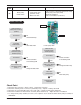
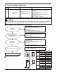
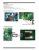
n AUUW36GD2 [MR36UY3J]
AC(N)-BLUE
AC(L)-BROWN
UVW
U,V,W CONNECTOR
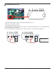
1. Wait until inverter PCB DC voltage is discharged after main power off.
2. Pull out AC(L), AC(N) connectors and U,V,W COMP Connector.
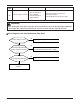
3. Set multi tester to resistance mode.
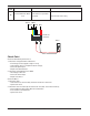
4.
If the value between P and N terminal of IPM is short(0Ω) or open(hundreds MΩ), PCB needs to be replaced.(IPM damaged)
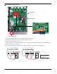
5. Set the multi tester to diode mode.
6. In case measured value is different from the table, PCB needs to be replaced.(PCB damaged).
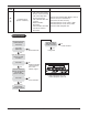
27 26 25 24 23 22 21
P W V U Nw Nv Nu P W V U Nw Nv Nu
0.4 ~ 0.6 V
27 26 25 24 23 22 21
0.4 ~ 0.6 V
PFC_IPM check
U, V, W ‘ R S T