
2014 960-914-06 (General SVC)


- 61 -
Only for training and service purposes
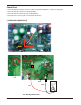
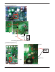
Check Point
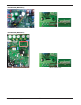
1. Check the WCN_P(L),P(N) Connection condition at the Main PCB.(Refer to outdoor wiring diagram)
2. Check the DC Link voltage at not operating(280V
↑
)
3. Check the DC Link voltage at Comp operating(340V
↑
)
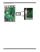
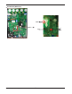
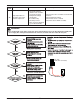
4. Check DC Link Sensing Signal :2.4~2.8V (Refer the Picture)
IN/I
GND
<CT Sensing Check Point>
Black
Red
Vdc
* AUUW24GD2 [MR24UY3J]