
2014 960-914-06 (General SVC)


- 73 -
Only for training and service purposes
Check Point
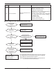
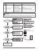
1. Check the Input Voltage (L1- L2 ‘ 230V±10%)
2. Check Input Voltage Sensor output voltage (2.5Vdc±10%)
Is Inverter PCB Normal?
No
Replace inverter PCB assembly
Is input voltage normal ?
No
Check L~N Voltage is 230V±15%
Yes
< Input Power Source Check Point >
Recheck power and
installation condition
Yes
n Error Diagnosis and Countermeasure Flow Chart
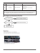
40
C/T
Sensor Error
• Initial current error
•
Malfunction of current detection circuit.
(Open / Short)
•
Check CT Sensor output voltage :
2.5Vdc ±5%
Display
code
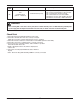
Title Cause of error Check point & Normal condition
WARNING
Before checking PCB or each outdoor electric parts, wait for 3 minutes after the power is off. When measuring at standby state
of power supply, after checking the measurement mode of the meter, be careful of the short-circuits with other parts.
n Error Diagnosis and Countermeasure Flow Chart