Models Indoor Unit MWM18Y3J MWM24Y3J Outdoor Unit MRM18Y3J MRM24Y3J 960-910-06
Operation Notices Content Precautions............................................................................................................1 Parts name ............................................................................................................2 Remote Screen Operation Guide Buttons on remote controller .................................................................................3 Introduction for icons on display screen .........................................................
Precautions Warning ● Do not connect air conditioner to multi-purpose socket.Otherwise, it may cause fire hazard ● Disconnect power supply when cleaning air conditioner. Otherwise, it may cause electric shock. ● Do not spray water on indoor unit. It may cause electric shock or malfunction. ● Do not spill or submerge remote controller in liquids, remote may malfunction or no longer operate. ● Do not repair air conditioner by yourself. It may cause electric shock or damage.
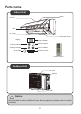
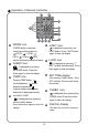
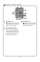
Parts name Indoor Unit panel air inlet filte air outlet horizontal louver display temp. indicator cooling indicator drying indicator heating indicator power indicator aux.button receiver window remote control Outdoor Unit air inlet handle handle air outlet Notice: Actual product may be different from above graphics, please refer to actual products.
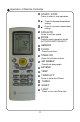
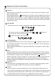
Operation of Remote Controller START / STOP 1 Press to start or stop operation. 2 : Press to decrease temperature setting. 3 : Press to increase temperature setting. FAN AUTO 4 Press to set fan speed. MODE 5 Press to select operation mode (AUTO/COOL/DRY/FAN/HEAT). 6 SENSOR 7 CLOCK Press to set clock. 8 1 2 AIR SWEEP 9 4 8 7 10 13 11 14 Press it set swing angle. 5 6 TIMER ON Press it to set auto-on timer.
Operation of Remote Controller 26 27 25 24 23 22 16 17 18 19 20 16 17 MODE icon: 20 is displayed by pressing the LIGHT button. Press LIGHT button again to clear the display. SLEEP icon : is displayed by pressing "+" and “-” buttons simultaneously. Press them again to clear the display.
Operation of Remote Controller 26 27 25 24 23 22 16 17 18 19 20 25 SENSOR icon: 27 is displayed when pressing the SENSOR button. Press this button again to clear the display. 26 21 EXTEND icon: is displayed when pressing the Press this button again to clear the display. EXTEND button. FAN SPEED display: Press FAN button to select the desired fan speed setting (AUTO- Low-Med-High).Your selection will be displayed in the LCD windows, except the AUTO fan speed.
Remote Control Instructions Remote Controller Description 1 START / STOP : Press this button to turn on the unit .Press this button again to turn off the unit. 2 3 Press this button to decrease set temperature. Hold it down for 2 seconds or more to rapidly decrease set temperature. In AUTO mode, set temperature is not adjustable. : Press this button to increase set temperature. Hold it down for 2 seconds or more to rapidly increase set temperature. In AUTO mode, set temperature is not adjustable.
Remote Control Instructions 8 TIMER ON : Press this button to initiate the auto-ON timer. To cancel the auto-timer program, simply press this button again. After pressing this button, disappears and "ON "blinks. 00:00 is displayed for ON time setting. Within 5 seconds, press + or - button to adjust the time value. Every press of either button changes the time setting by 1 minute. Holding down either button rapidly changes the time setting by 1 minute and then 10 minutes.
Remote Control Instructions 14 SLEEP: Press this button to go into the SLEEP operation mode. Press it again to cancel this function. This function is available in COOL or DRY mode to maintain the most comfortable temperature for you. 15 LIGHT: Press LIGHT button to turn on the display's light and press this button again to turn off the display's light. If the light is turned on, is displayed. If the light is tunrned off , disappears.
Emergency operation If remote controller is lost or damaged, please use auxiliary button to turn on or turn off the air conditioner. The operation in details are as below: As shown in the fig. press aux. button to turn on or turn o f the air conditioner. When the air conditioner is turned on, it will operate under auto mode. panel aux. button Clean and maintenance Note: ■ Turn off the air conditioner and disconnect the power before cleaning the air conditioner to avoid electric shock.
Clean and maintenance Clean filter 1 2 Open panel 3 Open panel to access filter. Clean filter ● Use vacuum or water to clean the filter. ● When the filter is very dirty, use warm water (below 113°F) to clean it, and then allow to dry. Remove filter Remove the filter as indicated in the fig. 4 Install filter Install the filter and then close the panel cover tightly. Note: ■ The filter should be cleaned every three months.
Clean and maintenance Pre-season check up 1. Check whether air inlets and air outlets are blocked. 2. Check whether circuit breaker is in good condition. 3. Check whether filter is clean 4. Check whether mounting bracket for outdoor unit is damaged or corroded. If yes, please contact dealer. 5. Check whether drainage pipe is damaged. Off-season check up 1. Disconnect power supply. 2. Clean filter and indoor unit s panel. 3. Check whether mounting bracket for outdoor unit is damaged or corroded.
Trouble Shooting Prior to calling for service please review troubleshooting section to eliminate any issues. Issue Check items Solution ● Check batteries ● Replace if needed. ● Ensure remote is within ● Receiving range for signal is ● Are there obstacles? ● Remove obstacles. ● Ensure remote is pointing ● Select proper angle and point the ● If no display on remote or ● Check and replace batteries. ● No display when operating ● Check check for damage to operating distance.
Trouble Shooting Check items Issue Solution ● Has there been a power failure? ● Wait for power to be restored. ● Are there lights on the display? ● If no check circuit breaker. ● Circuit breaker tripping? ● licensed professional. Air conditioner not operating ● Wires not attached? Call servicer or dealer for ● Call for immediate service.
Service and Assistance Issue Odors comming from system Check items Solution ● Check for source of odor. ● Eliminate the odor and clean filter. Air conditioner ● Check for inclimate weather or excessive wireless signals.
Trouble Shooting Error Code ● When air conditioner status is abnormal, temperature indicator on indoor unit will blink to display corresponding error code. Please refer to below list for identification of error code. Error code Indoor display Error code H1 Above indicator diagram is only for reference. Please refer to actual product for the actual indicator and position. Troubleshooting Unit is in defrost mode - This is normal. E5 Supply voltage was unstable during operation.
At least 6 in Space to the ceiling Installation dimension diagram Space to the wall At least 6 in At least 6 in Space to the wall Ft At least 8 Ft le 10 Space to the floo At t as At least 20 in Space to the obstruction Note *Min/Max Line Length 10'/82' At least 12 in Space to th e wall S o et c pa o the At At st lea Drainage pipe n tio uc tr bs the to n e ac ctio Sp stru in ob 12 t7 s lea At least 12 in Ft Space to the obstruction 16
Tools for installation 1. Level 2. Screw driver 3. Impact drill 4. Drill head 5. Pipe expander 6. Torque wrench 7. Open-end wrench 8. Pipe cutter 9. Leakage detector 10. Vacuum pump 11. Manifold gauges 12. Multimeter 13. Allen/spanner wrenches Note: 14. Measuring tape ● Please contact a local qualified installer for installation. ● Ensure power cords are rated for use with equipment.
Requirements for electric connection Safety precaution 1. Must follow national and regional safety regulations when installing the unit. 2. According to the local safety regulations, use qualified power supply circuit an circuit breaker. 3. Make sure the power supply matches with the requirement of air conditioner. Install proper power supply cables before using the air conditioner. 4. Properly connect all wires. 5.
Installation of indoor unit Step one: choosing installation location Step two: install wall bracket 1. Hang wall bracket, install center screw and apply level. 2. If required pre-drill in the locations you've chosen for mounting, install required mounting hardware and secure to wall. Step three: open piping hole 1. Choose the position of piping hole according to the direction of outlet pipe. The position of piping hole should be a little lower than the wall-mounted frame, shown as below.
Installation of indoor unit Indoor Note: outdoor ● Wall penetration collar is field supplied, ensure hole is properly insulated once unit is installed. ˜55 5-10 Step four: outlet pipe 2. When select leading out the pipe from left or right, please cut off the corresponding hole on the bottom case. 1. The pipe can be led out in the direction of right, rear right, left or rear left. left right left rear right rear left right cut off the hole Step five: connect the pipe of indoor unit 1.
Installation of indoor unit open-end wrench flare nut torque wrench pipe Hex nut diameter Tightening torque (N.m) Φ6 15~20 Φ 9.52 30~40 Φ 12 40~55 Φ 16 60~65 Φ 19 70~75 indoor pipe 4. Wrap with insulation then wrap with tape. Insulating pipe Step six: install drain hose 1. Connect the drain hose to the outlet pipe of indoor unit. drain hose outlet pipe 2. Bind the joint with hose clamp.
Installation of indoor unit 2. Make the power connection wire go through the cable-cross hole at the back of indoor unit and then pull it out from the front side. cable-cross hole power connection wire 3. Remove the wire clip; connect the power connection wire to the wiring terminal with wire clip. 18,24K indoor unit: N(1) 2 3 blue black brown yellowgreen Outdoor unit connection 4. Put wiring cover back and then tighten the screw. 5. Close the panel. Notice before installation 1.
Installation of indoor unit Step eight: bind up pipe 1. Bind up the connection pipe, power cord and drain hose with the band. indoor unit gas pipe connection pipe drain hose band indoor and outdoor power cord indoor power cord liquid pipe band 3. Bind them evenly. 4. The liquid pipe and gas pipe should be bound separately at the end. drain hose 2. Plan for bends in line set and ensure that cable and drain have extra length in those areas. Otherwise route these seperate from liquid and gas pipe.
Installation of outdoor unit Step one: securing of outdoor unit (select location based on actual application) 1. Select installation location to fit structure. Follow diagram and clearances. 2. Secure the outdoor unit on the selected location with expansion screws or required hardware. Note: ● Take sufficient protective measures whe installing the outdoor unit. ● Make sure the support can withstand at least four times of the unit weight.
Installation of outdoor unit Step three: fix outdoor unit foot holes 1. Place the outdoor unit on the support. 2. Fix the foot holes of outdoor unit with bolts. foot holes Step four: connect indoor and outdoor pipes 1. Remove the screw on the right handle of outdoor unit and then remove the handle. 2. Remove the screw cap of valve and attach the flare nut to the approriate valve. liquid pipe liquid valve screw handle pipe joint gas pipe flare nut gas valve 3. Pretightening the flare nut by hand.
Installation of outdoor unit Step five: connect outdoor electric wire 1. Remove the wire clip; connect the power connection wire and signal control wire (only for cooling and heating unit) to the wiring terminal according to the color; N(1) blue yellowgreen 2 black 3 L1 brown L2 G blue yellowgreen brown wire clamp power connect wire power cord 2. Secure the power connection wire and signal control wire with wire clip (only for cooling and heating unit).
Installation of outdoor unit Step six: neaten the pipes 1. The pipes should be placed along the wall, bent reasonably and hidden if possible. Min. radius of bend to the pipe is 4 in. 2. If the outdoor unit is higher than the wall penetration, you must set a U-shaped curve in the pipe before pipe goes into the room, in order to prevent rain from getting into the room. wall U-shaped curve drain hose Note: ● The through-wal height of drain hose shouldn't be higher than the outlet pipe hole of indoor unit.
Pressure testing Use Dry Nitrogen 1. Remove the valve caps on the liquid valve and gas valve and the nut of refrigerant port 2. Connect the charging hose of manifold to the refrigerant port, and the other to the nitrogen tank regulator. 3. (System should hold 550 Psig for one hour.) Begin witha. 150 psig for 5 min. b. 300 psig for 15 min. c. 550 psig for 1 hour. 4. Test all connections with bubble solution. 5. If no leaks are found proceed to vacuum steps below.
Vacuum pumping Use vacuum pump 1. Remove the valve caps on the liquid valve and gas valve and the nut of refrigerant port 2. Connect the charging hose liquid valve Manifold gauge Lo gas valve of manifold to the refrigerant refrigerant charging port, and the other to the port vacuum pump. nut of refrigerant 3. Open manifold and allow charging port valve cap vacuum to pump down for 20-30 min. Manifold should read -0.1MPa. vacuum pump Allen/spanner 4.
Check after installation ● Check according to the following requirement after finishing installation Items to be checked Possible malfunction Ensure unit has been installed correctly. The unit may drop, shake or emit noise. Has the system been leak tested? System will may not cool or heat properly. Has drain been properly insulated? It may cause condensation and water dripping. Is water draining well? It may cause condensation and water dripping.
Pipe expanding method Note: Improper pipe expanding is the main cause of refrigerant leakage. Please expand the pipe according to the following steps: A: Cut the pipe ● Confirm the pipe length according t the distance of indoor unit and outdoor unit. ● Cut pipe with pipe cutter. E: Expand the port ● Expand the port with expander.
Friedrich Air Conditioning Co. 10001 Reunion Place, Suite 500 • San Antonio, Texas 78216 1.800.541.6645 www.friedrich.