
Multi Zone Service Manual - General


5. Trouble Shooting
- 73 -
Only for training and service purposes
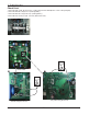
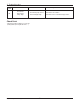
Check Point
1. Check the Input Voltage (L–N ‘ 220V±10%)
2. Check Input Voltage Sensor output voltage (2.5Vdc±10%)
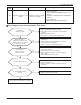
Is Inverter PCB Normal?
No
Replace inverter PCB assembly
Is input voltage normal ?
No
Check L~N Voltage is 220V±15%
Yes
< Input Power Source Check Point >
Recheck power and
installation condition
Yes
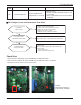
n Error Diagnosis and Countermeasure Flow Chart
40
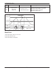
C/T
Sensor Error
• Initial current error
•
Malfunction of current detection circuit.
(Open / Short)
•
Check CT Sensor output voltage :
2.5Vdc ±5%
Display
code
Title Cause of error Check point & Normal condition