
Multi Zone Service Manual - General


5. Trouble Shooting
- 80 -
Only for training and service purposes
PFCM :
Measuring resistance
between No.19,20 pin
65
Heatsink High error
Inverter PCB heatsink
sensor is open or short
1. ODU fan locking
2. Heatsink assembly of INV PCB assemble
condition abnormal
3. Defect of temperature sensing circuit part defect
of INV PCB
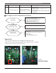
Display
code
Title Cause of error Check point & Normal condition
Is installation
condition normal ?
No
Yes
1. Check fan locking
2. Check covering of heat exchanger
3. Check distance between ODU and obstacles
4. Check pipe distortion and abnormality
5. Check service valve is opened
→ Eliminate causes for abnormal condition
Check resistance between NO.19 pin and NO.20 pin
of PFC module
Check resistance between NO.24 pin and NO.25 pin
of PFC module
→ 7KΩ ±10%(at 25°C)
→ Replace PCB if abnormality found
Is assemble condition
of INV PCB heatsink normal ?
Is PCB temperature
sensing part normal ?
No
No
Yes
Check assemble condition between INV PCB heatsink and
PFC & IPM module
→ Reassemble if abnormality found
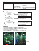
n Error Diagnosis and Countermeasure Flow Chart
Check Point
1. Check resistance between No.19 pin and NO.20 pin of PCB PFC module
2. Check resistance between No.24 pin and NO.25 pin of PCB PFC module - only 48/56k
3. Resistance value should be in 7kΩ ±10%.(at 25°C).
4. Check the PFC Module No.19, 20 and IPM Module No.24, 25 pin soldering condition.