
Multi Zone Service Manual - MR36TQY3JM
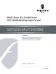
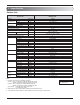
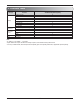
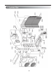
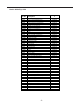

Table Of Contents

3. Piping Diagrams
Accumulator
Outdoor Unit
Reversing
Valve
Th1
Field piping
Gas(Ø3/8")
Room D
Room C
Room B
Room A
Th4
S/V
Th3
Heat
Exchanger
Field piping
Liquid(Ø1/4")
Room D
Room C
Room B
Room A
Main service
Valve(Gas)
EEV-D
EEV-C
EEV-B
EEV-A
Compressor
Th2
Main service
Valve(Liquid)
REFRIGERANT FLOW
COOLING
HEATING
LOC.
Description
PCB Connector
Th1
Thermistor for outdoor air temperature
CN_TH2
Th2
Thermistor for condensing temperature
CN_TH2
Th3
Thermistor for discharge pipe temperature
CN_TH3
Th4
Thermistor for suction pipe temperature
CN_TH3
S/V
Solenoid Valve for Hot Gas/Oil Separator
CN_H/GAS
/CN_OIL/S
L/P
Low Pressure Switch
CN_PRESS
- 4 -