
Accessory Installation Manual (2021, 2022)

Models PXSB23020/30 or 26515/20/30
920-114-02 R01 Friedrich Air Conditioning Co. Page 1/4
10001 Reunion Place, Suite 500 / San Antonio, Texas 78216
(210) 546-0500 / (800) 541-6645 / www.friedrich.com
Installation Instructions
Electrical Subbase Assembly
For Use with PTAC and PTHP Models
Please read these instructions completely before attempting installation.
NOTE: These instructions apply to the installation of the Electrical Subbase assembly.
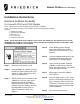
Contents:
1. Subbase Assembly
2. Side brackets, adjustable
3. Wire nuts (x 3)
4. #10 screws (x 4)
5. Installation instructions
NOTE: All electrical work must conform to local codes and ordinances, the national electrical code,
ANSI/NFPA NO. 70-1993 or current edition, and in Canada, the Canadian electrical code PART I, CSA
STANDARD C22.1-1993 or current edition.
Step 1. Disconnect ALL power to unit.
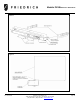
Step 2. Using Subbase as a guide, mark the
location for the mounting holes (See
Figure 2). Drill a 1/8” hole on each
side of the Wall Sleeve.
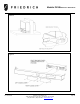
Step 3. Side brackets can be attached to the
subbase to cover the open space
between the wall and subbase.
Bend the bracket to size. Slip the
bracket inside the subbase and use
the adjustable mounting hole to
adjust fit against the wall. See
Figure 3.
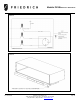
Step 4. Route building power through
knockouts provided for conduit
connectors into junction box. See
Figure 4.
Step 5. Connect building power wires to the
receptacle wires using wire nuts.
See Figure 5 for wiring diagram.
Step 6. Using screws provided, attached
subbase to wall sleeve using the
drilled holes from Step 2. Be careful
not to over tighten screws.
Step 7. Adjust legs to level the subbase.
See Figure 6.
Step 8. Remove Right access cover. Push
excess cord through opening on the
right. Plug the power cord into the
receptacle. Re-install access cover
making sure cord is routed through
notch in subbase.
Step 9. Re-connect power to unit