
Installation and Operation Manual (2019, 2020, 2021)

RT7
Manual Thermostat
The Friedrich RT7 is a non-
programmable electronic thermostat,
which can be used with the following
heating/cooling applications:
• Single Stage Heat - Cool PTAC Units
• Singe Stage Heat Pump PTAC Units
with or without Electric Heat
Installation and Operation Guide
• Input Voltage: 19 to 30 VAC
• Output Rating: Max. 1.5A per terminal (3A total)
• Temperature Control: 45°F to 90°F (7°C to 32°C)
• Temperature Accuracy: ± 1°F (± 0.5°C)
Specications
• This thermostat is for LOW voltage applications only.
• Turn OFF electricity to all heating and cooling components.
• All wiring must conform to applicable local and national building and electrical codes
and ordinances.
Safety Information
• Thermostat
• J-Box mounting plate/
decorative trim plate
• J-box mounting screws
• Dry wall anchors and mounting screws
• Wiring labels
• GL to GH Jumper wire
Included in Package
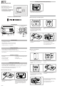
Parts Diagram
Opening
notch
(underneath)
Up button
Fan
Slide
Switch
Down button
Mode
Slide
Switch
Mounting directly on wall with trim plate
• If new mounting holes are needed, mark
the placement of the new horizontal
mounting holes through the trim plate
base. Using a 3/16" drill bit, drill the
holes you have marked and insert the
supplied wall anchors.
• Feed the wires through the back housing
of the thermostat and then snap the
back housing to the trim plate
• Your thermostat base should now be
securelyxedtothewall
• Feed the wires through the hole in the
trim plate and screw the trim plate to the
wall
• Useaatheadscrewdrivertoseparate
the front and back housing of the
thermostat
• If painting or construction is still ongoing, cover the thermostat completely or wait until
work is complete before mounting thermostat.
• Mountthethermostatonaninsidewallaboutvefeetabovetheoorinanareathat
hasgoodcirculationbutisnotdirectlyaectedbyaventorduct.
• Ensure power is switched OFF at the PTAC unit
Installing the Thermostat
Mounting directly on the wall
• Useaatheadscrewdrivertoseparate
the front and back housing of the
thermostat
• If new mounting holes are needed, mark
the placement of the new mounting holes
through the thermostat base. Using a
3/16" drill bit, drill the holes you have
marked and insert the supplied wall
anchors.
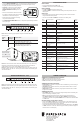
F
C
COOL HEAT
WAITOFF
E
RESET
Air Temp
Thermostat
mode
Fan status
indicator
Half degree for Celsius
Electric / Auxiliary Heat
Set tempLock
Status
Minimumo
time indicator
Heating/cooling
indicator
53624
Installing the Thermostat (continued)
• Feed the wires through the hole in the
back housing of the thermostat and then
screw the back housing to the wall
Mounting on Junction Box
• Install junction box
• Insert mounting screw into top of
junction box until there is approximately
1/8" gap between the screw head and
the wall
• Useaatheadscrewdrivertoseparate
the front and back housing of the
thermostat
• Feed the wires through the hole in the
trim plate and hang the trim plate on the
top screw
• Feed the wires through the back housing
of the thermostat and then snap the back
housing to the trim plate
• Your thermostat base should now be
securelyxedtothewall
• Insert and tighten the lower screw
• Ensurethattrimplateissecurelyttedto
the wall. If not, release lower screw and
tighten top screw.