
Installation and Operation Manual (2019, 2020, 2021)
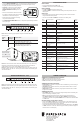

WIRING DIAGRAM: Heat Pump
HOW TO ENTER
• Place the Mode Slide Switch to OFF mode
• Hold UP for 5 seconds to enter the installer setting
HOW TO NAVIGATE
• Press UP or DOWN to change the setting value
• Hold UP or DOWN for 2 seconds to save the setting value and proceed to the next
setting option
HOW TO EXIT
• Whennished,leavethermostatwithoutpressinganybuttonsfor60secondsor
change Mode Slide Switch position
• Note: You must hold UP or DOWN for 2 seconds to save setting value
Menu
Number
Function Description Selectable Options Default
setting
01 Temperature Scale F: Fahrenheit
C: Celsius
F
02 Temperature Calibration +/- 5.4°F 0.0°F
03 (Not Used)
04 Max Heat Set Temp F: 60 to 90 (5°F step) 80°F
05 Min Cool Set Temp F: 60 to 80 (5°F step) 65°F
06 System Type H-C: Heat-Cool
HP: Heat Pump
H-C
07 (Not Used)
08 (Not Used)
09 Stage 1 Temperature
Control Swing
±0.25°F
±0.50°F
±1.00°F
±2.25°F
0.50°F
10 Auxiliary Stage Cut-In
Oset(onlyusedforHP
system type)
OFF (No Electric / Auxiliary heat)
-3.0 to -8.0°F (1°F step)
-4.0°F
11 (Not Used)
12 (Not Used)
13 (Not Used)
14 (Not Used)
15 (Not Used)
17 Always On Backlight OFF: 10s timeout
ON: always ON
OFF
18 Reset to default set
temperatures after each
mode change
ON: uses default temperatures after each mode
change (see menu 19 and 20)
OFF: Maintain last set temperature for each
mode
ON
19 Default heat mode set
temperature
60°F to Max Heat Set Temp 70°F
20 Default cool mode set
temperature
Min Cool Set Temp to 80°F 74°F
98 Minimumotime-
Compressor protection
NO:Immediateo/onswitching
YES:3-minuteminimumotimeenforced
NO
99 Reset NO: no reset
YES: ex-factory reset
NO
INSTALLER SETTINGS
THERMOSTAT SYSTEM MODE SWITCH POSITIONS:
• HEAT: thermostat permits heating operation
• OFF: thermostat stops all heating or cooling functions
• COOL: thermostat permits cooling operation
THERMOSTAT FAN SWITCH POSITIONS:
• AUTO position: fan operates in low speed mode as needed during a call for heating or
cooling activation only.
• LOW position: fanoperatescontinuouslyinlowspeed.Heat/Coolwillturnon/oin
background as needed.
• HIGH position:fanoperatescontinuouslyinhighspeed.Heat/Coolwillturnon/oin
background as needed.
THERMOSTAT BUTTONS:
• UP / DOWN: used for raising or lowering the target set temperature and selecting user
options and settings in the display screen.
• Note: toadjustthetargetsettemperature,rstensurethatthethermostatisin
either HEAT or COOL mode and press either UP or DOWN until the desired target
temperature is reached. Pressing UP or DOWNwillhavenoeectwhenthethermostat
is in OFF mode.
SETTING A KEYPAD / FRONT PANEL LOCKOUT:
• While in either HEAT or COOL mode, a keypad lockout can be introduced which will
prevent any temperature adjustment from being made by the user. Even while locked,
any button press will illuminate the display backlight.
• To activate (and deactivate) the keypad lockout, set Mode Slide Switch to either HEAT
or COOL, hold UP for 5 seconds . When the keypad is locked, a padlock will appear in
the lower left corner of the display.
NORMAL OPERATION
Friedrich Air Conditioning Co.
10001 Reunion Pl Suite 500,
San Antonio, TX 78216
1-877-599-5665
www.friedrich.com
Note 2: The “W2” terminal is used to call for Electric/Auxiliary heat. If your Heat Pump
PTAC does not have Electric heat, then the “W2” terminal should not be used and
InstallerSettingsmenu10(Aux.StageOset)shouldbesetto“OFF”.
Note 3: For PTAC units with only one fan speed (single “G” fan wire), add a jumper wire
to bridge together “GH” and “GL”. Connect your fan wire to either terminal after jumper
wire has been added.
Note 1: Make the following jumper position changes and Installer Settings for
Heat Pump units
System
Type
Changeover
valve type
Required action
Heat Pump B 1. Move yellow PCB jumper to HP position
2. Set Installer Settings Menu #06 to HP
O 1. Move yellow PCB jumper to HP position
2. Move blue PCB jumper to O position
3. Set Installer Settings Menu #06 to HP
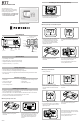
• Using the WIRING DIAGRAMS section, wire each terminal on the thermostat base.
Ensure that the bare end is fully seated into the connector, then tighten securely.
Pull gently on wires to ensure they are secure.
• Important: For Heat Pump systems additional
congurationstepsarenecessary.Viewthe
WIRING DIAGRAMS: Heat Pump section for
details.
• Return the thermostat front cabinet to its base
byhookingthetoprstandthengentlyswinging
the bottom of the thermostat into place.
• Restore power back to heating and cooling
components and thermostat.
• See INSTALLER SETTINGS MENU section, to adjust the required settings needed for
each system type.
B/O Y W2 R GH GL C
HP Valve Compressor 24V
Power
High
Speed
Fan
Low
Speed
Fan
24V
Common
Electric /
Auxiliary
Heat
Note 1: If connecting to a Cool only PTAC unit, the W1 wire terminals will not be used.
Note 2: For PTAC units with only one fan speed (single “G” fan wire), add a jumper wire
to bridge together “GH” and “GL”. Connect your fan wire to either terminal after jumper
wire has been added.
WIRING DIAGRAM: Heat - Cool
Y W1 R GH GL C
Cooling 24V
Power
High
Speed
Fan
Low
Speed
Fan
24V
Common
Heating
Move blue jumper
down for O valve
Move yellow jumper
down for Heat Pump