
Installation and Operation Manual

10
FRP011
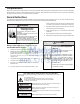
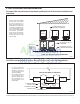
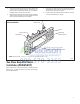
DRAIN TUBE
SIDE VIEW
FRONT VIEW
WALL SLEEVE
OPTIONAL AREA
PREFERRED AREA-
NO FOAM INSULATION
IF THE DRAIN MUST BE
LOCATED IN THE OPTIONAL
A
REA, THE FOAM INSULATION
MUST BE CUT AWAY AND
REMOVED TO ALLOW ACCESS
TO THE DRAIN.
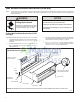
NUT
MOUNTING
PLATE
GASKET
SCREW
3"
Figure 11
Drain Kit Location and Installation
PXDR10
QUANTITY DESCRIPTION
2
1
1
3
4
2
2
COVER PLATES
MOUNTING PLATE
DRAIN TUBE
MOUNTING PLATE GASKET
#10 X ½” SHEET METAL SCREWS
#10-24 X ½ ” MACH. SCREWS
#10-24 X ½" LOCKNUTS
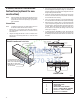
3. Remove the backing from the gasket and mount it on the at side
of the mounting plate. (See Figure 12, Page 11). Insert the drain
tube through the hole in the gasket and mounting plate so the tube
ange will be against the wall sleeve.
4. Position the assembly beneath the drilled holes and secure it with
#10-24 x ½" machine screws and lock nuts provided. Seal the tops
of the screws with silicone caulking.
5. Use ½" I.D. copper tube, PVC pipe, or vinyl hose (obtained locally)
to connect the internal drain tube to the drain system in the building.
6. Referring to Figure 12, Detail A, Page 11, locate and assemble the
(2) two cover plates and gaskets over the drain holes at the rear
of the wall sleeve. Attach them with the #10 sheet metal screws
provided. Make certain that the four overow slots at the rear of
the wall sleeve are not blocked (See drawing of the back of the
sleeve Figure 12, Page 11).
7. If a deep wall extension (PDXWSEXT) is used, after installing the
eld supplied ashing, caulk as required. Be sure to caulk around
the ashing and the wall sleeve where the hole was drilled for the
drain tube.
PXDR10 Drain Kit Installation
Instructions (optional for new
construction)
NOTE: Determine whether drain will be located within the wall, on the
indoor side, or will drain to the exterior of the building. Follow
appropriate instructions below depending on your particular
type of installation.
Internal Drain
NOTE: If installing an internal drain, you MUST install a drain kit on
the wall sleeve before the wall sleeve is installed.
1. Refer to Figure 11 and locate the drain within the “Preferred”
area of best drainage. Maintain at least a ½” clearance from the
embossed area.
2. Using the mounting plate with the ½” hole as a template, mark
and drill two, 3/16” mounting holes and a ½” drain hole in the
sleeve bottom.