
Installation and Operation Manual


15
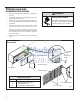
3. Route the cut ends of harness through the conduit connector
assembly and ex conduit sleeve. Be sure to use the supplied
conduit bushing to prevent damage to the cord by the conduit.
The cord should pass through the Locknut, Spacer, Chassis
Junction Box, Conduit Connector, Bushing, then the Conduit
Sleeve. See Figure 17.
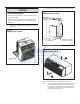
4. Route the cut ends of the power cord through the elbow connector
at the other end of the conduit. Tighten screws on elbow connector
to secure conduit sleeve.
5. Fasten and secure the elbow connector to the wall junction box
cover with locknut. Place and mount the wall junction box with
the four wall mounting screws making sure to pass the wall lines
through the junction box. Connect and join all wall lines with the
stripped ends using wire nuts. Tighten both screws of the wall
junction box cover to junction box.
6. Follow steps 4-6 on page 19 and refer to Figure 27.
Figure 15
Figure 16
Figure 17
FRP032
4.0 IN.
18.0 IN.
TRIM HARNESS
TO LENGTH
STRIP WIRE ENDS (0.5 IN.)
TO WALL JUNCTION
TO CHASSIS JUNCTION
EXPOSE
WIRES
(1.0 IN.)
FRP033
GROUND
SCREW
GROUND
WIRE
HARNESS
JUNCTION
BOX
WALL CONNECTION
JUNCTION
BOX COVER
COVER
SCREWS
STRAIGHT
CONNECTOR
FRP034
LOCKNUT
SPACER
SPACER
BUSHING
LEADING SIDE FOR
WIRE HARNESS INSERTION
EXITING SIDE FOR
WIRE HARNESS
CHASSIS
JUNCTION
BOX
CONDUIT
CONNECTOR
CONDUIT
SLEEVE