
Installation and Operation Manual


23
The adjustable control dip switches are located at the lower left hand portion of the digital Smart Center. The inputs are only visible and accessible with the
front cover removed from the PTAC.
Digital Control User Input Conguration
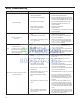
Switch Description Function Factory Setting Option
1 Emergency Heat Override
for PDH Heat Pump
Models
Enables electric heat only operation in the event of a com-
pressor failure on HP models.
Down - Normal Operation Up - Overrides compressor operation.
(PDH models only)
2 Wall Thermostat Switch Enables the use of a wall thermostat or unit controls Down - Unit Controls Up - Enables Wall Thermostat Usage
3 Fan Cycle for Heating Disabled (Refer to Constant Fan Mode) No Applicable No Applicable
4 Fan Cycle for Cooling Disabled (Refer to Constant Fan Mode) No Applicable No Applicable
5 Setpoint Switch 1 Allows the temperature setpoint range to be adjusted. Down 61F-86F Up 63F-80F Down 65F-78F Up 68F-75F
6 Setpoint Switch 2 Down (16C-30C) Down (18C-28C) Up (19C-26C) Up (20C-24C)
7 Room Freeze Protection Allows the unit to ensure the indoor room temperature does
not fall below 40F even when turned off.
Down - Freeze Protection Enabled Up - Freeze Protection Disabled
FRP028
DIP SWITCH
LOCATION OF
DIP SWITCHES
ON UNIT
123 4 5 6 7
Freeze guard
Setpoint Limit 2
Setpoint Limit 1
Fan CON/CYC for cooling
Fan CON/CYC for heating
Wall Thermostat enable
Electric heat only (for Heat Pumps)
UP
DOWN
High
Med
Low
Fan
Cool
Heat
Fan Speed Mode
Temperature
Power
Figure 31
Dip Switches
1. Emergency Heat Override – Switch 1
In the unlikely event of a compressor failure a heat pump unit may
be switched to operate in only the electric heat mode until repairs
can be made. Moving Dip Switch 1 to ‘ON’.
2. Wall Thermostat Switch 2
In order to enable the wall thermostat move Dip Switch to 'ON'.
3. Fan Cycle Control – Switch 3-4
Disabled (Refer to Constant Fan Mode)
4. Electronic Temperature Limiting – Switches 5-6
The digital control is set from the factory to allow a temperature
range between 61° F and 86° F in both heating and cooling
mode. Dip Switches 5-6 can be used to set high and low limits for
either heating both, cooling both or both.
From the factory switches are in the down 'OFF' position. The
chart below shows the available electronic limiting ranges.
5. Room Freeze Protection – Switch 7
Units are shipped from the factory with the room freeze protection
enabled. Room Freeze Protection can be switched off at the
owner’s preference by moving Dip Switch 7 to ‘OFF’. This feature
will monitor the indoor room conditions and in the event that the
room falls below 40°F the unit will cycle on high fan with the
electric heater. This occurs regardless of mode.
Dip Switch Setting