
Installation and Operation Manual

6
Wall Sleeve Installation Instructions (PDXWS)
NOTE: Insure that the unit is only installed in a wall structurally adequate to support the unit including the sleeve, chassis and accessories. If the sleeve
projects more than 8" into the room, a subbase or other means of support MUST be used. Please read these instructions completely before
attempting installation.
For Deep Wall Installation (Greater than 13 1/4")
See Page 9
The following instructions apply ONLY to walls less than 13 ¼" in depth.
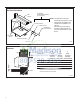
1. The PXDR10 Drain Kit (optional for new construction) see page 10
if applicable, must be installed before the wall sleeve is installed
into the wall.
2. The External Drain (for new construction or unit replacement) see
page 11, if applicable, must be installed before the wall sleeve is
installed into the wall.
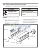
3. From inside the building, position the wall sleeve in the opening and
push it into the wall until it protrudes at least ¼” on the outside. Do
not allow sleeve to be pulled. (See Figure 11, Page 10).
4. Position the wall sleeve with a slight tilt towards the outside to
facilitate condensate drainage. It should be level side-to-side and
the front should be ¼ bubble higher than the back.
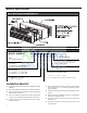
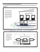
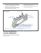
Figure 3
Typical Wall Sleeve Installation
NOTICE
DO NOT allow any pitch toward the inside.
Flashing on all 4 sides of the opening is recommended.
Potential property damage can occur if instructions are
not followed.
WARNING
Falling Object Hazard
Not following Installation Instructions for
mounting your air conditioner can result
in property damage, injury, or death.
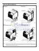
FRP008
20
"
MAX.
16-¼
"
42-¼
"
MIN.
LINTEL TO SUPPORT
MASONRY WALLS
ELECTRICAL
RECEPTACLE
ELECTRICAL
RECEPTACLE
WALL OPENING
WALL SLEEVE
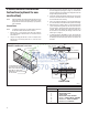
INSULATION
INSULATION
SMOOTH SIDE OF SCREW
CLIP FACING INTO ROOM
NOTE: All 230/208V units are manufactured with a 60” power cord and all 265V units with a 18” power cord.
60
"
MAX.
13-¾
"